
Machine Elements in Mechanical Design (6th Edition) (What's New in Trades & Technology)
6th Edition
ISBN: 9780134441184
Author: Robert L. Mott, Edward M. Vavrek, Jyhwen Wang
Publisher: PEARSON
expand_more
expand_more
format_list_bulleted
Concept explainers
Videos
Textbook Question
Chapter 3, Problem 77P
For the lever in P3−76, determine the maximum stress if the attachment point is moved to each of the other two holes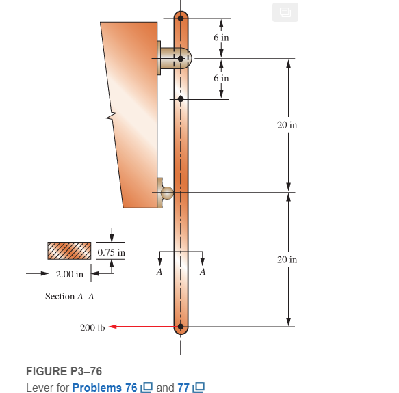
Expert Solution & Answer
Want to see the full answer?
Check out a sample textbook solution
Students have asked these similar questions
If the A-36 solid steel rod has a diameter of 50 mm and has been loaded with loadings as shown
in Figure Q4, determine the state of stress at point A and B and subsequently sketch their stress
elements.
An aluminum ring has an outside diameter of
12.0 mm and an inside diameter of 10 mm. If the
ring is short and is made of 2014-T6, compute the
3-13.
force required to produce ultimate compressive
failure in the ring. Assume that s, is the same in
both tension and compression.
Determine the equivalent stiffness constant of the ff.
Chapter 3 Solutions
Machine Elements in Mechanical Design (6th Edition) (What's New in Trades & Technology)
Ch. 3 - A tensile member in a machine structure is...Ch. 3 - Compute the stress in a round bar having a...Ch. 3 - Compute the stress in a rectangular bar having...Ch. 3 - A link in a packaging machine mechanism has a...Ch. 3 - Two circular rods support the 3800 lb weight of a...Ch. 3 - A tensile load of 5.00 kN is applied to a square...Ch. 3 - An aluminum rod is made in the form of a hollow...Ch. 3 - Compute the stress in the middle portion of rod AC...Ch. 3 - Compute the forces in the two angled rods in...Ch. 3 - If the rods from Problem 9 are circular, determine...
Ch. 3 - Repeat Problems 9 and 10 if the angle is 15 .Ch. 3 - Figure P312 shows a small truss spanning between...Ch. 3 - The truss shown in Figure P313 spans a total space...Ch. 3 - Figure P314 shows a short leg for a machine that...Ch. 3 - Consider the short compression member shown in...Ch. 3 - Refer Figure P38 . Each of the pins at A, B, and C...Ch. 3 - Compute the shear stress in the pins connecting...Ch. 3 - Prob. 18PCh. 3 - Prob. 19PCh. 3 - Prob. 20PCh. 3 - Prob. 21PCh. 3 - Compute the torsional shear stress in a circular...Ch. 3 - If the shaft of Problem 22 is 850 mm long and is...Ch. 3 - Compute the torsional shear stress due to a torque...Ch. 3 - Compute the torsional shear stress in a solid...Ch. 3 - Compute the torsional shear stress in a hollow...Ch. 3 - Compute the angle of twist for the hollow shaft of...Ch. 3 - A square steel bar, 25 mm on a side and 650 mm...Ch. 3 - A 3.00 in-diameter steel bar has a flat milled on...Ch. 3 - A commercial steel supplier lists rectangular...Ch. 3 - A beam is simply supported and carries the load...Ch. 3 - For each beam of Problem 31, compute its weight if...Ch. 3 - For each beam of Problem 31, compute the maximum...Ch. 3 - For the beam loading of Figure P334, draw the...Ch. 3 - For the beam loading of Figure P334, design the...Ch. 3 - Figure P336 shows a beam made from 4 in schedule...Ch. 3 - Select an aluminum I-beam shape to carry the load...Ch. 3 - Figure P338 represents a wood joist for a...Ch. 3 - For Problems 39 through 50, draw the free-body...Ch. 3 - Prob. 40PCh. 3 - For Problems 39 through 50, draw the free-body...Ch. 3 - Prob. 42PCh. 3 - Prob. 43PCh. 3 - Prob. 44PCh. 3 - For Problems 39 through 50, draw the free-body...Ch. 3 - For Problems 39 through 50, draw the free-body...Ch. 3 - For Problems 39 through 50, draw the free-body...Ch. 3 - For Problems 4850, draw the free-body diagram of...Ch. 3 - For Problems 4850, draw the free-body diagram of...Ch. 3 - Prob. 50PCh. 3 - Compute the maximum tensile stress in the bracket...Ch. 3 - Compute the maximum tensile and compressive...Ch. 3 - For the lever shown in Figure P353 (a), compute...Ch. 3 - Compute the maximum tensile stress at sections A...Ch. 3 - Prob. 55PCh. 3 - Refer to Figure P38. Compute the maximum tensile...Ch. 3 - Prob. 57PCh. 3 - Refer to P342. Compute the maximum stress in the...Ch. 3 - Refer to P343. Compute the maximum stress in the...Ch. 3 - Prob. 60PCh. 3 - Figure P361 shows a valve stem from an engine...Ch. 3 - The conveyor fixture shown in Figure P362 carries...Ch. 3 - For the flat plate in tension in Figure P363,...Ch. 3 - For Problems 64 through 68, compute the maximum...Ch. 3 - For Problems 64 through 68, compute the maximum...Ch. 3 - For Problems 64 through 68, compute the maximum...Ch. 3 - For Problems 64 through 68, compute the maximum...Ch. 3 - Prob. 68PCh. 3 - Figure P369 shows a horizontal beam supported by a...Ch. 3 - Prob. 70PCh. 3 - Prob. 71PCh. 3 - The beam shown in Figure P372 is a stepped, flat...Ch. 3 - Figure P373 shows a stepped, flat bar having a...Ch. 3 - Figure P374 shows a bracket carrying opposing...Ch. 3 - Prob. 75PCh. 3 - Figure P376 shows a lever made from a rectangular...Ch. 3 - For the lever in P376, determine the maximum...Ch. 3 - Figure P378 shows a shaft that is loaded only in...Ch. 3 - Prob. 79PCh. 3 - Prob. 80PCh. 3 - A hanger is made from ASTM A36 structural steel...Ch. 3 - A coping saw frame shown in Figure P382 is made...Ch. 3 - Prob. 83PCh. 3 - Figure P384 shows a hand garden tool used to break...Ch. 3 - Figure P385 shows a basketball backboard and goal...Ch. 3 - Prob. 86P
Knowledge Booster


Learn more about
Need a deep-dive on the concept behind this application? Look no further. Learn more about this topic, mechanical-engineering and related others by exploring similar questions and additional content below.Similar questions
- If load P = 22.1 kips, determine the normal force in bar (1).arrow_forwardRepeat Problem 11.2-3 assuming that R= 10 kN · m/rad and L = 2 m.arrow_forwardThe bell-crank mechanism is in equilibrium for an applied load of P = 24 kN. Assume that a = 300 mm, b = 235 mm, and θ = 55°. The pin at B has a diameter of d = 22 mm, and the bell crank has a thickness of t = 7 mm. Calculate the bearing stress in the bell crank at pin B.arrow_forward
- The bolt AB in (Figure 1) has a diameter of 18 mm and passes through a sleeve that has an inner diameter of 42 mm and an outer diameter of 52 mm. The bolt and sleeve are made of A-36 steel and are secured to the rigid brackets as shown. If the bolt length is 220 mm and the sleeve length is 200 mm, determine the tension in the bolt when a force of 50 kN is applied to the brackets.arrow_forward3-103: A circular rod with a diameter of 10.0 mm has a groove cut to a diameter of 8.0 mm. A full radius of 1.20 mm is produced at the bottom of the groove. Compute the maximum stress in the rod when an axial tensile force of 5500 N is applied.arrow_forwardThe uniform 300-1b bar AB carries a 500-lb vertical force at A. The bar is supported by a pin at B and the 0.5-in. diameter cable CD. Find the stress in the cable. DRAW THE FREE BODY DIAGRAM.arrow_forward
- In the figure shown below, set P = 48 lb, D1 = 8 in, D2 = 4 in, D3 = 4 in, and the bit diameter to 0.35 in. If the drill produces a torque T = 126 Ib*in, determine the normal stress along the z-axis for the element of material at point A, where the bit makes contact with the wall. Input your answer in units of ksi and be mindful of sign convention -e.i., tensile stresses are positive, compressive stresses are negative. areamstime D1 D2 y 4 3 dreaarrow_forwardDetermine the state of stress acting at point D. Take P₁ = 120 kN and P₂ = 45 kN. (Figure 1) Figure L -1.5m- +1.5m-1.5 m- 0.5 m 40 mm 100 mm 60 mm 80 mm 1 of 1 > Find op- Express your answer to three significant figures and include the appropriate units. Enter negative value in the case of compression and positive value in the case of tension. od= - 154.88 Submit Part B Previous Answers Request Answer X Incorrect; Try Again; 3 attempts remaining MPa Find TD- Express your answer to three significant figures and include the appropriate units. JA TD= Value Units ?arrow_forwardIf P is equivalent to 94 kN, the diameter at pin B is Blank 1 mm.arrow_forward
- The uniform 713 kg bar is supported by a smooth wall at A and by a pin at B that is in double shear. Determine the diameter of the smallest pin that can be used if its working shear stress is 42 MPa. Note: Gravitational acceleration is equal to 9.81 m/s2 LAB=6 m; L1=3.6 m.arrow_forward1-32 A control pedal for actuating a spring mechanism is shown in the figure. Calculate the shear stress in pins A and B due to force P when it causes a stress of 75 MPa in rod AB. Both pins are in double shear. Diameter of the Pin attached in the photo of the table provided below.arrow_forwardRN1 = 7921 round off maximum tension to the nearest whole numberarrow_forward
arrow_back_ios
SEE MORE QUESTIONS
arrow_forward_ios
Recommended textbooks for you
 Mechanics of Materials (MindTap Course List)Mechanical EngineeringISBN:9781337093347Author:Barry J. Goodno, James M. GerePublisher:Cengage Learning
Mechanics of Materials (MindTap Course List)
Mechanical Engineering
ISBN:9781337093347
Author:Barry J. Goodno, James M. Gere
Publisher:Cengage Learning
Hand Tools; Author: UCI Media;https://www.youtube.com/watch?v=4o0tqF0jDdo;License: Standard Youtube License