
Machine Elements in Mechanical Design (6th Edition) (What's New in Trades & Technology)
6th Edition
ISBN: 9780134441184
Author: Robert L. Mott, Edward M. Vavrek, Jyhwen Wang
Publisher: PEARSON
expand_more
expand_more
format_list_bulleted
Videos
Textbook Question
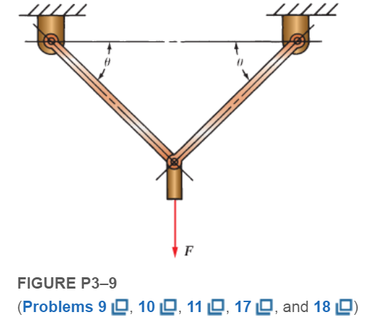
Chapter 3, Problem 9P
Compute the forces in the two angled rods in FigureP3−9for an applied force,
Expert Solution & Answer
Want to see the full answer?
Check out a sample textbook solution
Students have asked these similar questions
6 in
60°
20 in
Statics Instructor
A vertical force of P = 100 lb is required to remove the nail at C from the board. Determine the magnitude of the moment about B
exerted by the 100 lb vertical force.
Draw a free body diagram for the system. Then, use what you know about moments to solve for Mp
What is the magnitude of the moment at point B due to P if P = 100 lb and 9 = 10"? Round to the nearest whole number.
Enter a response then click Submit below
lb in
In the following armor find the forces in the members CD, KD and JK of section 1-1 indicated in the figure.
Compute the forces in the two angled rods in Figure below for an applied force, F = 1500 lb, if the angle u is 45°.
Chapter 3 Solutions
Machine Elements in Mechanical Design (6th Edition) (What's New in Trades & Technology)
Ch. 3 - A tensile member in a machine structure is...Ch. 3 - Compute the stress in a round bar having a...Ch. 3 - Compute the stress in a rectangular bar having...Ch. 3 - A link in a packaging machine mechanism has a...Ch. 3 - Two circular rods support the 3800 lb weight of a...Ch. 3 - A tensile load of 5.00 kN is applied to a square...Ch. 3 - An aluminum rod is made in the form of a hollow...Ch. 3 - Compute the stress in the middle portion of rod AC...Ch. 3 - Compute the forces in the two angled rods in...Ch. 3 - If the rods from Problem 9 are circular, determine...
Ch. 3 - Repeat Problems 9 and 10 if the angle is 15 .Ch. 3 - Figure P312 shows a small truss spanning between...Ch. 3 - The truss shown in Figure P313 spans a total space...Ch. 3 - Figure P314 shows a short leg for a machine that...Ch. 3 - Consider the short compression member shown in...Ch. 3 - Refer Figure P38 . Each of the pins at A, B, and C...Ch. 3 - Compute the shear stress in the pins connecting...Ch. 3 - Prob. 18PCh. 3 - Prob. 19PCh. 3 - Prob. 20PCh. 3 - Prob. 21PCh. 3 - Compute the torsional shear stress in a circular...Ch. 3 - If the shaft of Problem 22 is 850 mm long and is...Ch. 3 - Compute the torsional shear stress due to a torque...Ch. 3 - Compute the torsional shear stress in a solid...Ch. 3 - Compute the torsional shear stress in a hollow...Ch. 3 - Compute the angle of twist for the hollow shaft of...Ch. 3 - A square steel bar, 25 mm on a side and 650 mm...Ch. 3 - A 3.00 in-diameter steel bar has a flat milled on...Ch. 3 - A commercial steel supplier lists rectangular...Ch. 3 - A beam is simply supported and carries the load...Ch. 3 - For each beam of Problem 31, compute its weight if...Ch. 3 - For each beam of Problem 31, compute the maximum...Ch. 3 - For the beam loading of Figure P334, draw the...Ch. 3 - For the beam loading of Figure P334, design the...Ch. 3 - Figure P336 shows a beam made from 4 in schedule...Ch. 3 - Select an aluminum I-beam shape to carry the load...Ch. 3 - Figure P338 represents a wood joist for a...Ch. 3 - For Problems 39 through 50, draw the free-body...Ch. 3 - Prob. 40PCh. 3 - For Problems 39 through 50, draw the free-body...Ch. 3 - Prob. 42PCh. 3 - Prob. 43PCh. 3 - Prob. 44PCh. 3 - For Problems 39 through 50, draw the free-body...Ch. 3 - For Problems 39 through 50, draw the free-body...Ch. 3 - For Problems 39 through 50, draw the free-body...Ch. 3 - For Problems 4850, draw the free-body diagram of...Ch. 3 - For Problems 4850, draw the free-body diagram of...Ch. 3 - Prob. 50PCh. 3 - Compute the maximum tensile stress in the bracket...Ch. 3 - Compute the maximum tensile and compressive...Ch. 3 - For the lever shown in Figure P353 (a), compute...Ch. 3 - Compute the maximum tensile stress at sections A...Ch. 3 - Prob. 55PCh. 3 - Refer to Figure P38. Compute the maximum tensile...Ch. 3 - Prob. 57PCh. 3 - Refer to P342. Compute the maximum stress in the...Ch. 3 - Refer to P343. Compute the maximum stress in the...Ch. 3 - Prob. 60PCh. 3 - Figure P361 shows a valve stem from an engine...Ch. 3 - The conveyor fixture shown in Figure P362 carries...Ch. 3 - For the flat plate in tension in Figure P363,...Ch. 3 - For Problems 64 through 68, compute the maximum...Ch. 3 - For Problems 64 through 68, compute the maximum...Ch. 3 - For Problems 64 through 68, compute the maximum...Ch. 3 - For Problems 64 through 68, compute the maximum...Ch. 3 - Prob. 68PCh. 3 - Figure P369 shows a horizontal beam supported by a...Ch. 3 - Prob. 70PCh. 3 - Prob. 71PCh. 3 - The beam shown in Figure P372 is a stepped, flat...Ch. 3 - Figure P373 shows a stepped, flat bar having a...Ch. 3 - Figure P374 shows a bracket carrying opposing...Ch. 3 - Prob. 75PCh. 3 - Figure P376 shows a lever made from a rectangular...Ch. 3 - For the lever in P376, determine the maximum...Ch. 3 - Figure P378 shows a shaft that is loaded only in...Ch. 3 - Prob. 79PCh. 3 - Prob. 80PCh. 3 - A hanger is made from ASTM A36 structural steel...Ch. 3 - A coping saw frame shown in Figure P382 is made...Ch. 3 - Prob. 83PCh. 3 - Figure P384 shows a hand garden tool used to break...Ch. 3 - Figure P385 shows a basketball backboard and goal...Ch. 3 - Prob. 86P
Knowledge Booster


Learn more about
Need a deep-dive on the concept behind this application? Look no further. Learn more about this topic, mechanical-engineering and related others by exploring similar questions and additional content below.Similar questions
- 3-4 Sketch a free-body diagram of each element in the figure. Compute the magnitude and direction of each force using an algebraic or vector method, as specified. F=400 N. 30° B 60° 2 1.9 m 0 9 m C D 60° E xarrow_forward4. Forces F =F-20N and the third force F3 25N act on a cube with the side of a=2m. a. Find the screw driver (wrench) that is created by these forces i.e pitch, Mparallel, Mpapendicular b. Find the point of intersection of the axis of the wrench with the x-y plane. How do you check your answer is correct? G F D A B.arrow_forwardPractice Problem 3: Solve for the resultant force. F = 500 lb 30 45° F= 800 lbarrow_forward
- 3-1. Calculate the moment about point A (Figure P3–1). (Each section represents 1 ft2.) 26 lb//12 5. 34 lb 15 lb 3. 4 8. 15 30 lb FIGURE P3-1arrow_forwardConsider the frame shown in (Figure 1). Suppose that w = 5.5 kN/m Determine the x and y components of force that pin A exert on the frame using scalar notation. Determine the x and y components of force that pin B exert on the frame using scalar notation.arrow_forwardwith the following modifications: Add an additional force P = 20kN acting downwards at point Barrow_forward
- The rectangular framework is subjected to the following non-concurrent system of forces: a 30lb- force below the origin, a 20 lb-force,3ft above the origin and making an angle of30°N of E, a 100lb-force with a horizontal distance of 3ft and a vertical distance of 4ftfrom the origin and making an angle of 45°NW , a 60lb -force with the same distance like the previous force but along the positive x-axis, and a 100lb- force 4ft tothe right of the origin and making an angle of 60° S of W . Determine the magnitude and direction of the resultant, as well as its moment arm relative to the origin.arrow_forwardFind the tension in each of the supporting cables in the figure when the weight of the crate is 500 newtons.arrow_forwardFind the magnitude and direction of the resultant force for the system of forces shown in the figure. Where F1 =10 N, F2 =35N, F3 =30 N, F4 =10N, F5 %3D = 70N & F6 =70N. The angles 0, =25°, 03 =20° , 04 = 50°, 06 = 30 ° (Enter only the values in the boxes by referring the units given in bracket. Also upload the hand written copy in the link provided) F2 F3 F1 F6 F4 F5arrow_forward
arrow_back_ios
SEE MORE QUESTIONS
arrow_forward_ios
Recommended textbooks for you
 International Edition---engineering Mechanics: St...Mechanical EngineeringISBN:9781305501607Author:Andrew Pytel And Jaan KiusalaasPublisher:CENGAGE L
 Mechanics of Materials (MindTap Course List)Mechanical EngineeringISBN:9781337093347Author:Barry J. Goodno, James M. GerePublisher:Cengage Learning
International Edition---engineering Mechanics: St...
Mechanical Engineering
ISBN:9781305501607
Author:Andrew Pytel And Jaan Kiusalaas
Publisher:CENGAGE L
Mechanics of Materials (MindTap Course List)
Mechanical Engineering
ISBN:9781337093347
Author:Barry J. Goodno, James M. Gere
Publisher:Cengage Learning
Mechanical SPRING DESIGN Strategy and Restrictions in Under 15 Minutes!; Author: Less Boring Lectures;https://www.youtube.com/watch?v=dsWQrzfQt3s;License: Standard Youtube License