
Machine Elements in Mechanical Design (6th Edition) (What's New in Trades & Technology)
6th Edition
ISBN: 9780134441184
Author: Robert L. Mott, Edward M. Vavrek, Jyhwen Wang
Publisher: PEARSON
expand_more
expand_more
format_list_bulleted
Videos
Textbook Question
Chapter 3, Problem 38P
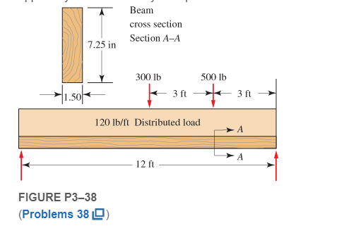
Figure P3−38 represents a wood joist for a platform, carrying a uniformly distributed load of 120 lb/ft and two concentrated loads applied by some machinery. Compute the maximum stress due to bending in the joist and the maximum vertical shear stress.
Expert Solution & Answer
Want to see the full answer?
Check out a sample textbook solution
Students have asked these similar questions
The beam is supported by a pin at point A and a roller at point C. A distributed load is applied to the beam.
Neglect the weight and thickness of the beam.
Hints:
1. will need to use similar triangles to find the height after sectioning at B.
2. Review direction of normal force, shear force and bending moment and which is positive or negative.
W2
W1
A
di
d2
Values for the figure are given in the following table. Note the figure may not be to scale.
Variable
Value
W1
190 N-m
W2
440 N-m
di
5 m
d2
5 m
a. Determine the magnitude of the normal force at point B, NB. .
b. Determine the magnitude of the shear force at point B, VB-
c. Is the shear force VB a positive or negative shear force?
d. Determine the magnitude of the bending moment at point B, MB.
e. Is the bending moment MB a positive or negative bending moment?
Round your final answers to 3 significant digits/figures.
Since the allowable normal stress of AC beam loaded with uniformly distributed load is 100MPa in tensile, 120MPa in compression and 50MPa in shear stress, check whether the beam is safe.
Since the allowable normal stress of AC beam loaded with uniformly distributed load is 100MPa in tension, 120MPa in compression and 50MPa in shear stress, check whether the beam is safe.
Chapter 3 Solutions
Machine Elements in Mechanical Design (6th Edition) (What's New in Trades & Technology)
Ch. 3 - A tensile member in a machine structure is...Ch. 3 - Compute the stress in a round bar having a...Ch. 3 - Compute the stress in a rectangular bar having...Ch. 3 - A link in a packaging machine mechanism has a...Ch. 3 - Two circular rods support the 3800 lb weight of a...Ch. 3 - A tensile load of 5.00 kN is applied to a square...Ch. 3 - An aluminum rod is made in the form of a hollow...Ch. 3 - Compute the stress in the middle portion of rod AC...Ch. 3 - Compute the forces in the two angled rods in...Ch. 3 - If the rods from Problem 9 are circular, determine...
Ch. 3 - Repeat Problems 9 and 10 if the angle is 15 .Ch. 3 - Figure P312 shows a small truss spanning between...Ch. 3 - The truss shown in Figure P313 spans a total space...Ch. 3 - Figure P314 shows a short leg for a machine that...Ch. 3 - Consider the short compression member shown in...Ch. 3 - Refer Figure P38 . Each of the pins at A, B, and C...Ch. 3 - Compute the shear stress in the pins connecting...Ch. 3 - Prob. 18PCh. 3 - Prob. 19PCh. 3 - Prob. 20PCh. 3 - Prob. 21PCh. 3 - Compute the torsional shear stress in a circular...Ch. 3 - If the shaft of Problem 22 is 850 mm long and is...Ch. 3 - Compute the torsional shear stress due to a torque...Ch. 3 - Compute the torsional shear stress in a solid...Ch. 3 - Compute the torsional shear stress in a hollow...Ch. 3 - Compute the angle of twist for the hollow shaft of...Ch. 3 - A square steel bar, 25 mm on a side and 650 mm...Ch. 3 - A 3.00 in-diameter steel bar has a flat milled on...Ch. 3 - A commercial steel supplier lists rectangular...Ch. 3 - A beam is simply supported and carries the load...Ch. 3 - For each beam of Problem 31, compute its weight if...Ch. 3 - For each beam of Problem 31, compute the maximum...Ch. 3 - For the beam loading of Figure P334, draw the...Ch. 3 - For the beam loading of Figure P334, design the...Ch. 3 - Figure P336 shows a beam made from 4 in schedule...Ch. 3 - Select an aluminum I-beam shape to carry the load...Ch. 3 - Figure P338 represents a wood joist for a...Ch. 3 - For Problems 39 through 50, draw the free-body...Ch. 3 - Prob. 40PCh. 3 - For Problems 39 through 50, draw the free-body...Ch. 3 - Prob. 42PCh. 3 - Prob. 43PCh. 3 - Prob. 44PCh. 3 - For Problems 39 through 50, draw the free-body...Ch. 3 - For Problems 39 through 50, draw the free-body...Ch. 3 - For Problems 39 through 50, draw the free-body...Ch. 3 - For Problems 4850, draw the free-body diagram of...Ch. 3 - For Problems 4850, draw the free-body diagram of...Ch. 3 - Prob. 50PCh. 3 - Compute the maximum tensile stress in the bracket...Ch. 3 - Compute the maximum tensile and compressive...Ch. 3 - For the lever shown in Figure P353 (a), compute...Ch. 3 - Compute the maximum tensile stress at sections A...Ch. 3 - Prob. 55PCh. 3 - Refer to Figure P38. Compute the maximum tensile...Ch. 3 - Prob. 57PCh. 3 - Refer to P342. Compute the maximum stress in the...Ch. 3 - Refer to P343. Compute the maximum stress in the...Ch. 3 - Prob. 60PCh. 3 - Figure P361 shows a valve stem from an engine...Ch. 3 - The conveyor fixture shown in Figure P362 carries...Ch. 3 - For the flat plate in tension in Figure P363,...Ch. 3 - For Problems 64 through 68, compute the maximum...Ch. 3 - For Problems 64 through 68, compute the maximum...Ch. 3 - For Problems 64 through 68, compute the maximum...Ch. 3 - For Problems 64 through 68, compute the maximum...Ch. 3 - Prob. 68PCh. 3 - Figure P369 shows a horizontal beam supported by a...Ch. 3 - Prob. 70PCh. 3 - Prob. 71PCh. 3 - The beam shown in Figure P372 is a stepped, flat...Ch. 3 - Figure P373 shows a stepped, flat bar having a...Ch. 3 - Figure P374 shows a bracket carrying opposing...Ch. 3 - Prob. 75PCh. 3 - Figure P376 shows a lever made from a rectangular...Ch. 3 - For the lever in P376, determine the maximum...Ch. 3 - Figure P378 shows a shaft that is loaded only in...Ch. 3 - Prob. 79PCh. 3 - Prob. 80PCh. 3 - A hanger is made from ASTM A36 structural steel...Ch. 3 - A coping saw frame shown in Figure P382 is made...Ch. 3 - Prob. 83PCh. 3 - Figure P384 shows a hand garden tool used to break...Ch. 3 - Figure P385 shows a basketball backboard and goal...Ch. 3 - Prob. 86P
Knowledge Booster


Learn more about
Need a deep-dive on the concept behind this application? Look no further. Learn more about this topic, mechanical-engineering and related others by exploring similar questions and additional content below.Similar questions
- Assignment 2 A Copper bar is loaded as shown complete the following: a. Draw a neat shear force and bending moment (Table of values is required) b. Calculate the maximum bending stress, clearly indicate where this occurs c. Calculate the maximum shear stress, clearly indicate where this occurs d. Plot the bending and shear stress for the cross section at x= 4 ft. from the left hand support. Clearly show the calculations were made at the following positions: y-0, 2, 4, 6, 8, 10 and 12 35 Ib/ft. 200 Ib Beam cross section 12 65" 8 ft. 5ft. 3 ft.arrow_forward4) The C-clamp shown below has rectangular cross-section A-A that is 33 mm tall by 12 mm wide and the material is class 50 gray cast iron. Determine maximum tensile stress and factor of safety for clamping force F = 3.2 kN. Ignore stress concentration factors. See Section 4.9 in Norton for help with curved beams. MPa N O MAX |F F 60 mm 40 mm 12 mm 33 mm 33 mm Section A-A Aarrow_forwardTask 1 (a) A steel cantilever beam with a 1-in-diameter round cross section and length of 10 in is loaded at the tip with a transverse force of 1000 lbf and an axial force of 5000 lbf, as shown in the figure. Study the significance of the transverse shear stress in combination with tension and bending by calculating magnitudes of the stresses. Explain and comment on the stresses and strains generated. 1000 Ibf 1 in dia. Cross section at the wall 5000 Ibf (b) Consider a square element in the x-y plane with side length of 3 cm. The thickness of the element is 7 mm. The element has modulus of elasticity of 200 GPa and Poison's ratio of 0.33. If the element is subjected to forces in the x and y directions of 3 KN and 1.5 KN, respectively, find the dimensions of the loaded element. (c) Consider a cubic element with side length of 4 cm. The element has modulus of elasticity of 80 GPa and Poison's ratio of 0.3. If the element is subjected to equal forces in the x, y and z direction of 3 KN.…arrow_forward
- Find the equations for load forces, shear forces, and bending moment diagrams. Draw the shear and moment diagram.arrow_forwardQuestion 5 Calculate the maximum longitudinal direct stress, plot the stress distribution diagram and determine the location of the neutral axis for a 20 long simply supported beam with a rectangularcross-section that is 160 mm wide and 210 mm deep, which carries a uniformly distributed load of 260 N/m, on its upper surface and a compressive axial load of 220 kN at its free ends. Present schematics showing the distribution of bending direct longitudinal stress, direct load stress, the combined longitudinal direct stress, and identify the neutral axis as well as centroidal axis on the schematic. Show the values of these stresses at the top and bottom surfaces of the cross-section.arrow_forwarda 80 mm wide and 300 mm high simply supported bean has a length of 7.4 m and supports a concentrated load of 7.2 kN acting at the midspan. Find the maximum shear stress and maximum bending stress.arrow_forward
- Q3:To determine bending moment values at all load points and supports. Also draw BMD.arrow_forwardThe beam in Figure 1; (a) Draw the Normal Force Diagram. (b) Draw the shear force diagram. (c) Draw the bending moment diagram. şekil 1 = figure 1 L1(m)=1.0 , L2(m)=1.4 , L3(m)=1.2 , M(kN.m)=20 , P(kN)=9 , q(kN/m)=8arrow_forwardDraw bending moment diagram for the loading shown in Figure Q15arrow_forward
- A WT305 x 41 standard steel shape is used to support the loads shown. Assume w = 40 kN/m, LAB = 2.0 m, LBc = 4.0 m, and Lco = 2.0 m. Consider the entire 8.0 m length of the beam and determine: (a) the maximum tensile bending stress at any location along the beam (enter a positive answer), and (b) the maximum compressive bending stress at any location along the beam (enter a negative answer). B D LAB LBC LCD WT305 x 41 Answer: MPa (a) Omax.T MPa (b) ơmax.C=arrow_forwardProblem 1: In the figure below a solid bar with a 1.00 in diameter is subjected to a bending moment M and a twisting moment T. Given that the magnitude of the twisting moment and the bending moment are equal, so that M = T₁ answer the following questions: M a) If the bar is made from a material that undergoes brittle failure under a tensile stress of 6000 psi, what is the value of the minimum moment that would produce brittle failure? Make a sketch of the bar; then determine and show the direction of the fracture plane with respect to the axial direction of the bar. Draw Mohr's circle and show your work. b) If the bar is made from a ductile material that yields plastically at a stress of 36000 psi, what is the value of the minimum moment that would produce yielding? Use von-Mises theory.arrow_forwardFind reactions and plot shear force and bending moment diagramsarrow_forward
arrow_back_ios
SEE MORE QUESTIONS
arrow_forward_ios
Recommended textbooks for you
 Mechanics of Materials (MindTap Course List)Mechanical EngineeringISBN:9781337093347Author:Barry J. Goodno, James M. GerePublisher:Cengage Learning
Mechanics of Materials (MindTap Course List)
Mechanical Engineering
ISBN:9781337093347
Author:Barry J. Goodno, James M. Gere
Publisher:Cengage Learning
Mechanics of Materials Lecture: Beam Design; Author: UWMC Engineering;https://www.youtube.com/watch?v=-wVs5pvQPm4;License: Standard Youtube License