
Machine Elements in Mechanical Design (6th Edition) (What's New in Trades & Technology)
6th Edition
ISBN: 9780134441184
Author: Robert L. Mott, Edward M. Vavrek, Jyhwen Wang
Publisher: PEARSON
expand_more
expand_more
format_list_bulleted
Concept explainers
Videos
Textbook Question
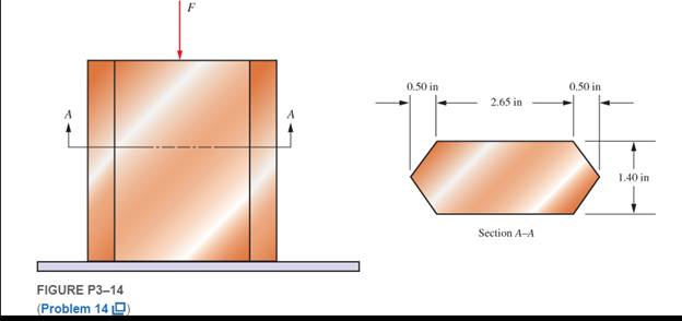
Chapter 3, Problem 14P
Figure P3−14 shows a short leg for a machine that carries a direct compression load. Compute the compressive stress if the cross section has the shape shown and the applied force is
Expert Solution & Answer
Want to see the full answer?
Check out a sample textbook solution
Students have asked these similar questions
A small seat angle is used to support a beam with a reaction of 6,000 lbs. Two 1/2 inchdiameter bolts are used to resist the load. Compute the stress in each bolt.
I'm having a hard time with this problem can you help?
Compute the forces in the two angled rods in Figure below for an applied force, F = 1500 lb, if the angle u is 45°.
For the figure shown below, compute the shear force in section 1. Neglect the weights of the member. Note
that point B is pin-connected.
50KN
...
2m.
B
5m
5m
5m
Chapter 3 Solutions
Machine Elements in Mechanical Design (6th Edition) (What's New in Trades & Technology)
Ch. 3 - A tensile member in a machine structure is...Ch. 3 - Compute the stress in a round bar having a...Ch. 3 - Compute the stress in a rectangular bar having...Ch. 3 - A link in a packaging machine mechanism has a...Ch. 3 - Two circular rods support the 3800 lb weight of a...Ch. 3 - A tensile load of 5.00 kN is applied to a square...Ch. 3 - An aluminum rod is made in the form of a hollow...Ch. 3 - Compute the stress in the middle portion of rod AC...Ch. 3 - Compute the forces in the two angled rods in...Ch. 3 - If the rods from Problem 9 are circular, determine...
Ch. 3 - Repeat Problems 9 and 10 if the angle is 15 .Ch. 3 - Figure P312 shows a small truss spanning between...Ch. 3 - The truss shown in Figure P313 spans a total space...Ch. 3 - Figure P314 shows a short leg for a machine that...Ch. 3 - Consider the short compression member shown in...Ch. 3 - Refer Figure P38 . Each of the pins at A, B, and C...Ch. 3 - Compute the shear stress in the pins connecting...Ch. 3 - Prob. 18PCh. 3 - Prob. 19PCh. 3 - Prob. 20PCh. 3 - Prob. 21PCh. 3 - Compute the torsional shear stress in a circular...Ch. 3 - If the shaft of Problem 22 is 850 mm long and is...Ch. 3 - Compute the torsional shear stress due to a torque...Ch. 3 - Compute the torsional shear stress in a solid...Ch. 3 - Compute the torsional shear stress in a hollow...Ch. 3 - Compute the angle of twist for the hollow shaft of...Ch. 3 - A square steel bar, 25 mm on a side and 650 mm...Ch. 3 - A 3.00 in-diameter steel bar has a flat milled on...Ch. 3 - A commercial steel supplier lists rectangular...Ch. 3 - A beam is simply supported and carries the load...Ch. 3 - For each beam of Problem 31, compute its weight if...Ch. 3 - For each beam of Problem 31, compute the maximum...Ch. 3 - For the beam loading of Figure P334, draw the...Ch. 3 - For the beam loading of Figure P334, design the...Ch. 3 - Figure P336 shows a beam made from 4 in schedule...Ch. 3 - Select an aluminum I-beam shape to carry the load...Ch. 3 - Figure P338 represents a wood joist for a...Ch. 3 - For Problems 39 through 50, draw the free-body...Ch. 3 - Prob. 40PCh. 3 - For Problems 39 through 50, draw the free-body...Ch. 3 - Prob. 42PCh. 3 - Prob. 43PCh. 3 - Prob. 44PCh. 3 - For Problems 39 through 50, draw the free-body...Ch. 3 - For Problems 39 through 50, draw the free-body...Ch. 3 - For Problems 39 through 50, draw the free-body...Ch. 3 - For Problems 4850, draw the free-body diagram of...Ch. 3 - For Problems 4850, draw the free-body diagram of...Ch. 3 - Prob. 50PCh. 3 - Compute the maximum tensile stress in the bracket...Ch. 3 - Compute the maximum tensile and compressive...Ch. 3 - For the lever shown in Figure P353 (a), compute...Ch. 3 - Compute the maximum tensile stress at sections A...Ch. 3 - Prob. 55PCh. 3 - Refer to Figure P38. Compute the maximum tensile...Ch. 3 - Prob. 57PCh. 3 - Refer to P342. Compute the maximum stress in the...Ch. 3 - Refer to P343. Compute the maximum stress in the...Ch. 3 - Prob. 60PCh. 3 - Figure P361 shows a valve stem from an engine...Ch. 3 - The conveyor fixture shown in Figure P362 carries...Ch. 3 - For the flat plate in tension in Figure P363,...Ch. 3 - For Problems 64 through 68, compute the maximum...Ch. 3 - For Problems 64 through 68, compute the maximum...Ch. 3 - For Problems 64 through 68, compute the maximum...Ch. 3 - For Problems 64 through 68, compute the maximum...Ch. 3 - Prob. 68PCh. 3 - Figure P369 shows a horizontal beam supported by a...Ch. 3 - Prob. 70PCh. 3 - Prob. 71PCh. 3 - The beam shown in Figure P372 is a stepped, flat...Ch. 3 - Figure P373 shows a stepped, flat bar having a...Ch. 3 - Figure P374 shows a bracket carrying opposing...Ch. 3 - Prob. 75PCh. 3 - Figure P376 shows a lever made from a rectangular...Ch. 3 - For the lever in P376, determine the maximum...Ch. 3 - Figure P378 shows a shaft that is loaded only in...Ch. 3 - Prob. 79PCh. 3 - Prob. 80PCh. 3 - A hanger is made from ASTM A36 structural steel...Ch. 3 - A coping saw frame shown in Figure P382 is made...Ch. 3 - Prob. 83PCh. 3 - Figure P384 shows a hand garden tool used to break...Ch. 3 - Figure P385 shows a basketball backboard and goal...Ch. 3 - Prob. 86P
Knowledge Booster


Learn more about
Need a deep-dive on the concept behind this application? Look no further. Learn more about this topic, mechanical-engineering and related others by exploring similar questions and additional content below.Similar questions
- A link in an automated packaging machine is a hollow tube made from 6061-T6 aluminum. Its dimensions are as follows: outside diameter = 32.0 mm, inside diameter = 28.0 mm, and length = 1.00 m. Compute the tensile force required to produce an elongation of the bar of 1.3 mm. Would the stress produced by the force just found be safe if the load is applied repeatedly?arrow_forwardA tractor weighing 80 kN was lifted by 3 cables as shown in the figure. Calculate the stress on the AB cablearrow_forwardThe figure shows a flat hanger bar for supporting shop equipment in a factory. The bar is fixed to a support by means of a bolted connection. The main part of the hanging bar is 1.5 inches wide. This width varies up to 3.0 inches. A 1.0-inch diameter bolt transfers the hanger bar load to the two top bracket plates. Determine the allowable stress of the tension load P in the hanger in the following two instances: to. The allowable tensile stress in the main part of the hanger is 16,000 psi. b. The allowable stress load between the hanger bar and the bolt is 26,000 lb/pu.arrow_forward
- A 3/8-inch diameter bolt is subjected to a 2,085-lb tensile load. The bolt passes through a very thick plate to restrain it. Compute the tensile stress in the bolt. Your Answer:arrow_forwardAnswer Problem 6-22 from P. 271 of your textbook and the additional questions below, assuming the stress in cable AB is within the proportional limit. Include a carefully labelled free-body diagram for the pipe strut as part of your solution. Show all work.arrow_forwardCompute the maximum stress in the member, considering stress concentrations. Use Figure P3-66 2.00-in dia. 0.10-in radius 1.25-in dia. Applied torque = 2200 lb-inarrow_forward
- a short link in a mechanism carries an axial compressive load of 3500 N. if it has a square cross section 8.0 mm on a side, compute the stress in the linkarrow_forwardWhen a force P of 750 N is applied to the pedal shown in the figure, find the diameter of this chip as mm so that the resulting shear stress on the pin at C is 40 MP.arrow_forwardA square pedestal has glued parts at joints t, r, e, and s. Plane t-r-e-s is at anole of 30° from the vertical axis Given the following data: allowable pressive stress of 5.2 MPa in glued joint and Shear stress of 3.5 MPa. If the axial pedestal force is 36 kN. determine the safe width dimension in mm and the angle in degrees if the maximum shear stress will occur to the plane.arrow_forward
- A steel rod 8 mm in diameter is under the action of a tensile force (P) of 600 Newton. Calculate the tensile stress (s) acting in the bar. Solve for Mpa (round up to whole number)arrow_forward3. Calculate the bearing stress and shear stress between the pin and each bracket of a clevis joint. Assume pin diameter of 10 mm, 40 mm wide gap link, 12 mm thick bracket, and 3550N tensile load. Draw a free body diagram (geometry & forces) Identify stress plane Calculate stress and write it (with appropriate units) in the outlined boxarrow_forwardFigure 2: Given the below determine the bar force at BD. (Answer in whole number, indicate the answer in kN. just input the value, do this for all the questions on Figure 2) Note: if the member is in compression, write a negative symbol before it, ex: 12kn in compression is answer:-12arrow_forward
arrow_back_ios
SEE MORE QUESTIONS
arrow_forward_ios
Recommended textbooks for you
 Mechanics of Materials (MindTap Course List)Mechanical EngineeringISBN:9781337093347Author:Barry J. Goodno, James M. GerePublisher:Cengage Learning
Mechanics of Materials (MindTap Course List)
Mechanical Engineering
ISBN:9781337093347
Author:Barry J. Goodno, James M. Gere
Publisher:Cengage Learning
Understanding Shear Force and Bending Moment Diagrams; Author: The Efficient Engineer;https://www.youtube.com/watch?v=C-FEVzI8oe8;License: Standard YouTube License, CC-BY
Bending Stress; Author: moodlemech;https://www.youtube.com/watch?v=9QIqewkE6xM;License: Standard Youtube License