
Machine Elements in Mechanical Design (6th Edition) (What's New in Trades & Technology)
6th Edition
ISBN: 9780134441184
Author: Robert L. Mott, Edward M. Vavrek, Jyhwen Wang
Publisher: PEARSON
expand_more
expand_more
format_list_bulleted
Concept explainers
Videos
Textbook Question
Chapter 3, Problem 82P
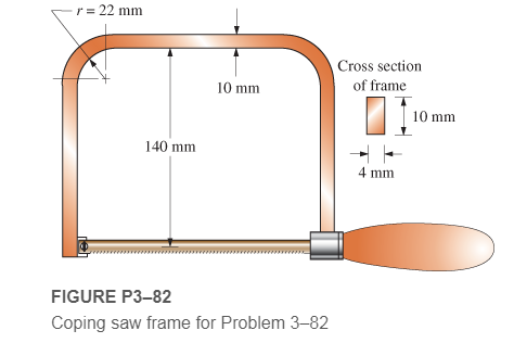
A coping saw frame shown in Figure P3−82 is made from SAE 1020 CD steel. A screw thread in the handle draws the blade of the saw into a tension of 120 N. Determine the resulting design factor based on yield strength in the area of the corner radii of the frame.
Expert Solution & Answer
Want to see the full answer?
Check out a sample textbook solution
Students have asked these similar questions
The figure below is a schematic drawing of a shaft that supports two V-belt pulleys. The loose belt tension on the pulley at A is 15% of the tension on the tight side. The shaft material has a yield strength of 300 MPa and an ultimate tensile strength of 520 MPa. Calculate the shaft diameter.
A steel rod is subjected to a reversed axial load of 180 kN. Find the diameter of the rod for a factor of safety of 2. Neglect column action. The material has an ultimate tensile strength of 1070 MPa and yield strength of 910 MPa. The endurance limit in reversed bending may be assumed to be one-half of the ultimate tensile strength. Other correction factors may be taken as follows: For axial loading (Ka) = 0.7; For machined surface (Ksur) = 0.8 ; For size (Ksz) = 0.85 ; For stress concentration(Kf)= 1.0.3.
The figure below shows a boat propeller mounted on a drive shaft with a 7 mm diameter (d) cylindrical drive pin inserted through the hub
and the shaft. The drive shaft diameter, D, inside the hub is 69 mm. The pin is made from AISI 1020 cold rolled steel, which has a yield stress
of 427 MPa and an ultimate stress of 621 MPa. If the drive pin is subjected to an overload (e.g. strikes a log), calculate the torque (Nm)
required to shear the pin.
Note: Assume that the max shear stress of the pin material is approximately equal 82% of the ultimate tensile stress.
Do not include units in your answer.
Pin
F
Hub
Drive
pin
Shaft
Drive
shaft
F
Shear
planes
Hub
Answer:
Chapter 3 Solutions
Machine Elements in Mechanical Design (6th Edition) (What's New in Trades & Technology)
Ch. 3 - A tensile member in a machine structure is...Ch. 3 - Compute the stress in a round bar having a...Ch. 3 - Compute the stress in a rectangular bar having...Ch. 3 - A link in a packaging machine mechanism has a...Ch. 3 - Two circular rods support the 3800 lb weight of a...Ch. 3 - A tensile load of 5.00 kN is applied to a square...Ch. 3 - An aluminum rod is made in the form of a hollow...Ch. 3 - Compute the stress in the middle portion of rod AC...Ch. 3 - Compute the forces in the two angled rods in...Ch. 3 - If the rods from Problem 9 are circular, determine...
Ch. 3 - Repeat Problems 9 and 10 if the angle is 15 .Ch. 3 - Figure P312 shows a small truss spanning between...Ch. 3 - The truss shown in Figure P313 spans a total space...Ch. 3 - Figure P314 shows a short leg for a machine that...Ch. 3 - Consider the short compression member shown in...Ch. 3 - Refer Figure P38 . Each of the pins at A, B, and C...Ch. 3 - Compute the shear stress in the pins connecting...Ch. 3 - Prob. 18PCh. 3 - Prob. 19PCh. 3 - Prob. 20PCh. 3 - Prob. 21PCh. 3 - Compute the torsional shear stress in a circular...Ch. 3 - If the shaft of Problem 22 is 850 mm long and is...Ch. 3 - Compute the torsional shear stress due to a torque...Ch. 3 - Compute the torsional shear stress in a solid...Ch. 3 - Compute the torsional shear stress in a hollow...Ch. 3 - Compute the angle of twist for the hollow shaft of...Ch. 3 - A square steel bar, 25 mm on a side and 650 mm...Ch. 3 - A 3.00 in-diameter steel bar has a flat milled on...Ch. 3 - A commercial steel supplier lists rectangular...Ch. 3 - A beam is simply supported and carries the load...Ch. 3 - For each beam of Problem 31, compute its weight if...Ch. 3 - For each beam of Problem 31, compute the maximum...Ch. 3 - For the beam loading of Figure P334, draw the...Ch. 3 - For the beam loading of Figure P334, design the...Ch. 3 - Figure P336 shows a beam made from 4 in schedule...Ch. 3 - Select an aluminum I-beam shape to carry the load...Ch. 3 - Figure P338 represents a wood joist for a...Ch. 3 - For Problems 39 through 50, draw the free-body...Ch. 3 - Prob. 40PCh. 3 - For Problems 39 through 50, draw the free-body...Ch. 3 - Prob. 42PCh. 3 - Prob. 43PCh. 3 - Prob. 44PCh. 3 - For Problems 39 through 50, draw the free-body...Ch. 3 - For Problems 39 through 50, draw the free-body...Ch. 3 - For Problems 39 through 50, draw the free-body...Ch. 3 - For Problems 4850, draw the free-body diagram of...Ch. 3 - For Problems 4850, draw the free-body diagram of...Ch. 3 - Prob. 50PCh. 3 - Compute the maximum tensile stress in the bracket...Ch. 3 - Compute the maximum tensile and compressive...Ch. 3 - For the lever shown in Figure P353 (a), compute...Ch. 3 - Compute the maximum tensile stress at sections A...Ch. 3 - Prob. 55PCh. 3 - Refer to Figure P38. Compute the maximum tensile...Ch. 3 - Prob. 57PCh. 3 - Refer to P342. Compute the maximum stress in the...Ch. 3 - Refer to P343. Compute the maximum stress in the...Ch. 3 - Prob. 60PCh. 3 - Figure P361 shows a valve stem from an engine...Ch. 3 - The conveyor fixture shown in Figure P362 carries...Ch. 3 - For the flat plate in tension in Figure P363,...Ch. 3 - For Problems 64 through 68, compute the maximum...Ch. 3 - For Problems 64 through 68, compute the maximum...Ch. 3 - For Problems 64 through 68, compute the maximum...Ch. 3 - For Problems 64 through 68, compute the maximum...Ch. 3 - Prob. 68PCh. 3 - Figure P369 shows a horizontal beam supported by a...Ch. 3 - Prob. 70PCh. 3 - Prob. 71PCh. 3 - The beam shown in Figure P372 is a stepped, flat...Ch. 3 - Figure P373 shows a stepped, flat bar having a...Ch. 3 - Figure P374 shows a bracket carrying opposing...Ch. 3 - Prob. 75PCh. 3 - Figure P376 shows a lever made from a rectangular...Ch. 3 - For the lever in P376, determine the maximum...Ch. 3 - Figure P378 shows a shaft that is loaded only in...Ch. 3 - Prob. 79PCh. 3 - Prob. 80PCh. 3 - A hanger is made from ASTM A36 structural steel...Ch. 3 - A coping saw frame shown in Figure P382 is made...Ch. 3 - Prob. 83PCh. 3 - Figure P384 shows a hand garden tool used to break...Ch. 3 - Figure P385 shows a basketball backboard and goal...Ch. 3 - Prob. 86P
Knowledge Booster


Learn more about
Need a deep-dive on the concept behind this application? Look no further. Learn more about this topic, mechanical-engineering and related others by exploring similar questions and additional content below.Similar questions
- Repeat Problem 11.3-9. Use two C 150 × 12.2 steel shapes and assume that E = 205 GPa and L = 6 m.arrow_forwardCompare the angle of twist 1 for a thin-walled circular tube (see figure) calculated from the approximate theory for thin-walled bars with the angle of twist 2 calculated from the exact theory of torsion for circular bars, Express the ratio 12terms of the non-dimensional ratio ß = r/t. Calculate the ratio of angles of twist for ß = 5, 10, and 20. What conclusion about the accuracy of the approximate theory do you draw from these results?arrow_forwardA stepped bar with a hole (see figure) has widths h = 2.4 in. and c = 1.6 in. The fillets have radii equal to 0.2 in. What is the diameter d max of the largest hole that can be drilled through the bar without reducing the load-carrying capacity?arrow_forward
- A solid circulai' aluminum bar AB is fixed at both ends and loaded by a uniformly distributed torque 150N·n/m. The bar has diameter d = 30 mm. Calculate the reactive torques at the supports and the angle of twist at midspan. Assume that G = 28 GPa.arrow_forwardRequlred Informatlon A rotating shaft of 25-mm dlameter Is simply supported by bearing reaction forces R;and R2. The shaft is loaded with a transverse load of 13 kN as shown In the figure. The shaft is made from AISI 1045 hot-rolled steel. The surface has been machined. NOTE: This is a multi-part question. Once an answer is submitted, you will be unable to return to this part. 200 mm 25 mm 13 kN -50 mm Not to acale Determine the minimum fatigue factor of safety based on achleving Infinite life. The minimum fatigue factor of safety isarrow_forwardLink 2, shown in the figure, is 25 mm wide and 11 mm thick. It is made from low-carbon steel with Sy= 165 MPa. The pin joints are constructed with sufficient size and fit to provide good resistance to out-of-plane bending. Use Table 4-2 shown below for recommended values for C. Determine the following for link 2: a.)Axial Force b.)Yield factor of safety c.) In-plane buckling factor of safety and Out-plane buckling factor of safetyarrow_forward
- 4) Ball bearings support the rotating axle shown below at points A and D. The rotating axle is loaded by a stationary (non-rotating) force of F = 6.8 kN. In the drawing below, all dimensions are in mm, and all geometry changes (steps in the diameter shaft) have a fillet radius of 3 mm. The axle is machined from AISI cold-drawn steel with an ultimate strength of S_u = 690 MPa and a yield strength of S_y= 580 MPa. Calculate the safety factor at the 6.8 kN load and points B and C, which experience moderate bending moments with a geometric feature that causes a stress concentration. Determine the number of cycles to failure of this part. 30 -10 -250 32 B 6.8 KN 75 -38 100- с 125 10 35 D 30arrow_forwardthe propeller on a ship shown in figure qi is subjected to a compressive axial force f of 180 kn as it pushes the water backward and a torsional load t of 15 kn.m as it turns through the water. the solid shaft has a diameter of 150 mm. it is made of c1018 steel with yield strength of 220 mpa, young's modulus of 200 gpa and poisson's ratio of 0.3. a) at the most critical material point of the shaft, calculate the stress state and sketch the corresponding stress element. b) what is the factor of safety of the shaft if it is designed according to:i) tresca criterion?ii) von mises criterion? c) by sketching the principal stresses on the tresca and von mises yield loci, briefly explain the reason for the difference in the factor of safety according to both criteria. d) without performing any calculation, would the factor of safety become higher, lower or the same according to tresca criterion if a hollow shaft with an inner diameter of 130 mm and an outer diameter of 150 mm of the same…arrow_forwardThe connecting rod in the figure is 10mm thick and manufactured from 8580M30 steel by cold drawing. The bar is threaded through the holes, loaded with fully variable load from the pins. Find the maximum load F to be applied to the part so that the part can have an indefinite life by looking at the appropriate figures for the stress concentrations that will occur due to the notch and drill hole.(Sut=600MPa,Sy=470Mpa)arrow_forward
- 1) Ball bearings support the rotating axle shown below at points A and D. The rotating axle is loaded by a stationary (non-rotating) force of F = 6.8 kN. In the drawing below, all dimensions are in mm. While the real part has fillets (r=3mm), you can assume an abrupt change in geometry for each shaft step for this problem. The axle is machined from AISI cold-drawn steel with an ultimate strength of S_u = 690 MPa, a yield strength of S_y=580 MPa, and a modulus of Elasticity of E_steel = 207 GPa. Determine the displacement at the 6.8 kN load and points B and C. 6.8 KN 30 10 250 32 B 75 38 100 10-1 -35 30arrow_forwardA Component shown in figure below machined from a plate of steel C45 having ultimate strength as 630 MPa, yield stress as 540 MPa and endurance strength 225 MPa. It is subjected to a completely revered axial load from -50 kN to +50 kN and the factor of safety is 2. Determine the plate thickness having width as 100 mm by using soderberg fatigue equation.arrow_forwardA part is loaded with a combination of bending, axial, and torsion such that the following stresses are created at a particular location: Bending - Completely reversed, with a maximum stress of 60 MPa Axial - Constant stress of 20 MPa Torsion - Repeated load, varying from 0 MPa to 50 MPa Assume the varying stresses are in phase with each other. The part contains a notch such that Kibending = 1.4, Kaxial = 1.1, and K. = 2.0. The material properties are Sy = 300 MPa and S, = 400 MPa. The completely adjusted endurance limit is found to be Se= 200 MPa. Find the factor of safety for fatigue based on infinite life. If the life is not infinite, estimate the number of cycles. Be sure to check for yielding. f,torsionarrow_forward
arrow_back_ios
SEE MORE QUESTIONS
arrow_forward_ios
Recommended textbooks for you
 Mechanics of Materials (MindTap Course List)Mechanical EngineeringISBN:9781337093347Author:Barry J. Goodno, James M. GerePublisher:Cengage Learning
Mechanics of Materials (MindTap Course List)
Mechanical Engineering
ISBN:9781337093347
Author:Barry J. Goodno, James M. Gere
Publisher:Cengage Learning
Stresses Due to Fluctuating Loads Introduction - Design Against Fluctuating Loads - Machine Design 1; Author: Ekeeda;https://www.youtube.com/watch?v=3FBmQXfP_eE;License: Standard Youtube License