
Machine Elements in Mechanical Design (6th Edition) (What's New in Trades & Technology)
6th Edition
ISBN: 9780134441184
Author: Robert L. Mott, Edward M. Vavrek, Jyhwen Wang
Publisher: PEARSON
expand_more
expand_more
format_list_bulleted
Concept explainers
Videos
Textbook Question
Chapter 3, Problem 78P
Figure P3−78 shows a shaft that is loaded only in bending. Bearings are located at points B and D to allow the shaft to rotate. Pulleys at A, C, and E carry cables that support loads from below while allowing the shaft to rotate. Compute the maximum stress due to bending in the shaft considering stress concentrations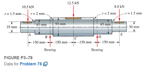
Expert Solution & Answer
Want to see the full answer?
Check out a sample textbook solution
Chapter 3 Solutions
Machine Elements in Mechanical Design (6th Edition) (What's New in Trades & Technology)
Ch. 3 - A tensile member in a machine structure is...Ch. 3 - Compute the stress in a round bar having a...Ch. 3 - Compute the stress in a rectangular bar having...Ch. 3 - A link in a packaging machine mechanism has a...Ch. 3 - Two circular rods support the 3800 lb weight of a...Ch. 3 - A tensile load of 5.00 kN is applied to a square...Ch. 3 - An aluminum rod is made in the form of a hollow...Ch. 3 - Compute the stress in the middle portion of rod AC...Ch. 3 - Compute the forces in the two angled rods in...Ch. 3 - If the rods from Problem 9 are circular, determine...
Ch. 3 - Repeat Problems 9 and 10 if the angle is 15 .Ch. 3 - Figure P312 shows a small truss spanning between...Ch. 3 - The truss shown in Figure P313 spans a total space...Ch. 3 - Figure P314 shows a short leg for a machine that...Ch. 3 - Consider the short compression member shown in...Ch. 3 - Refer Figure P38 . Each of the pins at A, B, and C...Ch. 3 - Compute the shear stress in the pins connecting...Ch. 3 - Prob. 18PCh. 3 - Prob. 19PCh. 3 - Prob. 20PCh. 3 - Prob. 21PCh. 3 - Compute the torsional shear stress in a circular...Ch. 3 - If the shaft of Problem 22 is 850 mm long and is...Ch. 3 - Compute the torsional shear stress due to a torque...Ch. 3 - Compute the torsional shear stress in a solid...Ch. 3 - Compute the torsional shear stress in a hollow...Ch. 3 - Compute the angle of twist for the hollow shaft of...Ch. 3 - A square steel bar, 25 mm on a side and 650 mm...Ch. 3 - A 3.00 in-diameter steel bar has a flat milled on...Ch. 3 - A commercial steel supplier lists rectangular...Ch. 3 - A beam is simply supported and carries the load...Ch. 3 - For each beam of Problem 31, compute its weight if...Ch. 3 - For each beam of Problem 31, compute the maximum...Ch. 3 - For the beam loading of Figure P334, draw the...Ch. 3 - For the beam loading of Figure P334, design the...Ch. 3 - Figure P336 shows a beam made from 4 in schedule...Ch. 3 - Select an aluminum I-beam shape to carry the load...Ch. 3 - Figure P338 represents a wood joist for a...Ch. 3 - For Problems 39 through 50, draw the free-body...Ch. 3 - Prob. 40PCh. 3 - For Problems 39 through 50, draw the free-body...Ch. 3 - Prob. 42PCh. 3 - Prob. 43PCh. 3 - Prob. 44PCh. 3 - For Problems 39 through 50, draw the free-body...Ch. 3 - For Problems 39 through 50, draw the free-body...Ch. 3 - For Problems 39 through 50, draw the free-body...Ch. 3 - For Problems 4850, draw the free-body diagram of...Ch. 3 - For Problems 4850, draw the free-body diagram of...Ch. 3 - Prob. 50PCh. 3 - Compute the maximum tensile stress in the bracket...Ch. 3 - Compute the maximum tensile and compressive...Ch. 3 - For the lever shown in Figure P353 (a), compute...Ch. 3 - Compute the maximum tensile stress at sections A...Ch. 3 - Prob. 55PCh. 3 - Refer to Figure P38. Compute the maximum tensile...Ch. 3 - Prob. 57PCh. 3 - Refer to P342. Compute the maximum stress in the...Ch. 3 - Refer to P343. Compute the maximum stress in the...Ch. 3 - Prob. 60PCh. 3 - Figure P361 shows a valve stem from an engine...Ch. 3 - The conveyor fixture shown in Figure P362 carries...Ch. 3 - For the flat plate in tension in Figure P363,...Ch. 3 - For Problems 64 through 68, compute the maximum...Ch. 3 - For Problems 64 through 68, compute the maximum...Ch. 3 - For Problems 64 through 68, compute the maximum...Ch. 3 - For Problems 64 through 68, compute the maximum...Ch. 3 - Prob. 68PCh. 3 - Figure P369 shows a horizontal beam supported by a...Ch. 3 - Prob. 70PCh. 3 - Prob. 71PCh. 3 - The beam shown in Figure P372 is a stepped, flat...Ch. 3 - Figure P373 shows a stepped, flat bar having a...Ch. 3 - Figure P374 shows a bracket carrying opposing...Ch. 3 - Prob. 75PCh. 3 - Figure P376 shows a lever made from a rectangular...Ch. 3 - For the lever in P376, determine the maximum...Ch. 3 - Figure P378 shows a shaft that is loaded only in...Ch. 3 - Prob. 79PCh. 3 - Prob. 80PCh. 3 - A hanger is made from ASTM A36 structural steel...Ch. 3 - A coping saw frame shown in Figure P382 is made...Ch. 3 - Prob. 83PCh. 3 - Figure P384 shows a hand garden tool used to break...Ch. 3 - Figure P385 shows a basketball backboard and goal...Ch. 3 - Prob. 86P
Knowledge Booster


Learn more about
Need a deep-dive on the concept behind this application? Look no further. Learn more about this topic, mechanical-engineering and related others by exploring similar questions and additional content below.Similar questions
- Repeat Problem 9,5-15 for the anti-symmetric loading shown in the figure.arrow_forwardRepeat Problem 6.2-1 but now assume that the steel plate is smaller (0.5 in. × 5 in.) and is aligned with the top of the beam as shown in the figure.arrow_forwardRepeat Problem 3.3-1, but now use a circular tube with outer diameter d0= 2.5 in. and inner diameter di= 1.5 in.arrow_forward
- A plumber's valve wrench is used to replace valves in plumbing fixtures. A simplified model of the wrench (see figure part a) consists of pipe AB (length L. outer diameter D inner diameter dy), which is fixed at A and has holes of a diameter dhon either side of the pipe at B. A solid, cylindrical bar CBD (lengths, diameter^) is inserted into the holes at B and only one force F = 55 lb is applied in the -Z direction at C to loosen the fixture valve at A (see figure part c). Let G = 11,800 ksi, v = 0.30, L = 4 in., a = 4.5 in., d2= 1.25 in., dx= 1 in., and dh= 0.25 in. Find the state of plane stress on the top of the pipe near A (at coordinates A" = 0,Y = Q,Z = d->12), and show all stresses on a plane stress element (see figure part b). Compute the principal stresses and maximum shear stress, and show them on properly rotated stress elementsarrow_forwardRepeat Problem 2.3-4, but now include the weight of the bar. Sec Table 1.1 in Appendix I for the weight density of steel.arrow_forward-15 Repeat the preceding problem using ??. = - 750 psi.arrow_forward
- A steel punch consists of two shafts: upper shaft and lower shaft. Assume that the upper shaft has a diameter d1= 24 mm and the bottom shaft has a diameter d2= 16 mm. The punch is used to insert a hole in a 4 mm plate, as shown in the figure. If a force P - 70 kN is required to create the hole, what is the average shear stress in the plate and the average compressive stress in the upper and lower shaft of the punch?arrow_forwardA circular tube of aluminum is subjected to torsion by torques T applied at the ends (see figure). The bar is 24 in. long, and the inside and outside diameters are 1.25 in. and 1.75 in., respectively. It is determined by measurement that the angle of twist is 4° when the torque is 6200 lb-in. Calculate the maximum shear stress in the tube, the shear modulus of elasticity G, and the maximum shear strain (in radians). If the maximum shear strain in the tube is limited to 2.5 × 10⁻³ and the inside diameter is increased to 1.375 in., what is the maximum permissible torque?arrow_forwardThe propeller shaft of a large ship has an outside diameter 18 in. and inside diameter 12 in,, as shown in the figure. The shaft is rated for a maximum shear stress of 4500 psi. If the shaft is turning at 100 rpm, what is the maximum horsepower that can be transmitted without exceeding the allowable stress? If the rotational speed of the shaft is doubled but the power requirements remain unchanged, what happens to the shear stress in the shaft?arrow_forward
arrow_back_ios
SEE MORE QUESTIONS
arrow_forward_ios
Recommended textbooks for you
 Mechanics of Materials (MindTap Course List)Mechanical EngineeringISBN:9781337093347Author:Barry J. Goodno, James M. GerePublisher:Cengage Learning
Mechanics of Materials (MindTap Course List)
Mechanical Engineering
ISBN:9781337093347
Author:Barry J. Goodno, James M. Gere
Publisher:Cengage Learning
Solids: Lesson 53 - Slope and Deflection of Beams Intro; Author: Jeff Hanson;https://www.youtube.com/watch?v=I7lTq68JRmY;License: Standard YouTube License, CC-BY