
Videos
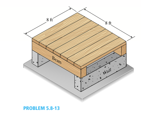
A square wood platform is 8 ft × 8 ft in area and rests on masonry walls (see figure). The deck of the platform is constructed of 2-in. nominal thickness tongue-and-groove planks (actual thickness 1.5 in.; sec Appendix CL) supported on two S-ft long beams. The beams have 4 in. × (i in. nominal dimensions (actual dimensions 3.5 in. × 5.5 in.).
The planks arc designed to support a uniformly distributed load n ( lb/ft" i acting over the entire top surface of the platform. I be allowable bending stress for the planks is 2400 psi and the allowable shear stress is 100 psi. W ben analyzing the planks, disregard their weights and assume that their reactions are uniformly distributed over the top surfaces of the supporting beams.
(a) Determine the allowable platform load Mr. (lb/ft2) based upon the bending stress in the planks.
(b) Determine the allowable platform load if-. (lb/ft-) based upon the shear stress in the planks.
(c) Which of the preceding values becomes the allowable load alolow on the platform?
Hints: Use care in constructing the loading diagram for the planks, noting especially that the reactions are distributed loads instead of concentrated loads. Also, note that the maximum shear forces occur at the inside faces of the supporting beams.

Trending nowThis is a popular solution!

Chapter 5 Solutions
Mechanics of Materials (MindTap Course List)


- (c) The cross section of a quarter circular concrete block XYZof width 1.8m is shown in Figure 3. The specific weight of the concrete mix is 24 kN/m3. The hinge is along XX. Calculate the vertical force R at Y to hold the gate in this position. K Fixed slab 1.2 m Y W Fy 1.3 m FĦ D B Figure 3arrow_forwardRequlred Informatlon A cantilevered beam is loaded as shown. The cross section at the wall is shown, with points of interest A (at the top). B (at the center), and C(midway between A and B). - 200 mm- 50 mm B 50 mm Cross section at wall where F= 2.2 kN NOTE: This is a multi-part question. Once an answer is submitted, you will be unable to return to this part. Calculate the magnitudes of the stresses acting on the stress elements. Do not neglect transverse shear stress. The magnitude of stresses acting on the stress elements are as follows: At element A, MPa and TA= MPa At element B. OB- MPa and T8= MPа At element C. MPa and IC= MPaarrow_forward2. A simply supported rectangular concrete beam of span 8m has to be prestressed with a force of 1600 kN. The tendon is of parabolic profile having zero eccentricity at the supports. The beam has to carry an external uniformly distributed load of intensity 30 kN/m. Neglecting the self- weight of the beam, the maximum dip (in meters, up to two decimal places) of the tendon at the mid-span to balance the external load should be? Span of the beam, L = 8m Prestressing force, P = 1600 kN %3D U.D.L. on the beam, w = 30 kN/m Maximum dip of tendon to balance the external load e = ?arrow_forward
- A new art exhibit featuring mobile works is going up in the Norwalk, CA area. One art work is shown in the figure below. A 105 N uniform beam is pinned to the ground by a pivot. The beam is supported by a cable (attached 3/5 from the bottom of the beam) to allow for each of the shoes to hang freely. Each individual shoe has a weight of 7.5 N. 10 WALL FLOR (a) ( If one shoe is attached 1/7 of the way up the beam and another shoe is attached 5/8 of the way up the beam, with e, = 70.1° and e, 30.1°, what is the tension in the cable, in newtons? %3! %3D (b) What is the x-component of the force, in newtons, that the pivot exerts on the bottom of the beam? (c) O What is the y-component of the force, in newtons, that the pivot exerts on the bottom of the beam?arrow_forwardQ2: A simply supported beam has a span of 4m and carries a uniformly distributed load of 60 kN/m together with a central concentrated load of 40 kN. Draw the S.F. and B.M. diagrams for the beam, (see Figure (1)). 40KN 60KN/m Figure (1)arrow_forwardThe figure below shows two solid homogenous rectangular beam sections with (breadth x depth) dimensions in two different orientations as follows: Beam Section Orientation A (t mm x 2t mm); and Beam Section Orientation B (2t mm x tmm). Both beams sag when subjected to the same loading and support conditions resulting in compressive stresses above the centroid line (neutral axis). Which statement accurately describes the relative maximum compressive stress (ocompression) between these beam section orientations? O a. O b. Oc tmm 2 mm Beam Section Orientation A 2tmm 7 mm Beam Section Orientation B Maximum compressive stress (compression) in orientation B is greater than orientation A by a factor of 2. Maximum compressive stress (ocompression) in orientation A is greater than orientation B by a factor of 4. Maximum compressive stress (compression) in orientation B is greater than orientation A by a factor of 4. O d. Maximum compressive stress (ocompression) in orientation A is greater than…arrow_forward
- The Straw Hat crew on their journey to Laugh Tale Island found a big treasure box (W). Luffy wanted to place the treasure box (W) as shown in the figure. A 100-mm x 300 mm rectangular beam is supported in a horizontal position. At point "A", it is being held by a pin and at "B" by a cable BD inclined 3 vertical to 4 horizontal. Assume all forces are applied to the beam along its central axis. Given that Fcparallel to grain = 10.50 MPa, W = 79 kN and E = 13800 MPa. Neglecting the weight of the beam and cable, determine whether the design is safe. Cable 2.4 m 2.4 marrow_forwardThe figure below shows two solid homogenous rectangular beam sections with (breadth x depth) dimensions in two different orientations as follows: Beam Section Orientation A (t mm x 2t mm); and Beam Section Orientation B (2t mm x t mm). Both beams sag when subjected to the same loading and support conditions resulting in compressive stresses above the centroid line (neutral axis). Which statement accurately describes the relative maximum compressive stress (ocompression) between these beam section orientations? t mm 2t mm 2t mm t mm Beam Section Orientation A Beam Section Orientation B O a. Maximum compressive stress (ocompression) in orientation A is greater than orientation B by a factor of 4. O b. Maximum compressive stress (ocompression) in orientation B is greater than orientation A by a factor of 2. O c. Maximum compressive stress (ocompression) in orientation B is greater than orientation A by a factor of 4. O d. Maximum compressive stress (ocompression) in orientation A is…arrow_forwardA small balcony constructed of wood issupported by three identical cantilever beams (seefigure). Each beam has length L1 = 2.1m, width b,and height h = 4b/3. The dimensions of the balconyfloor are L1 XL2, where L2 = 2.5 m. The designload is 5.5 kPa acting over the entire floor area.(This load accounts for all loads except the weightsof the cantilever beams, which have a weight densityΥ = 5.5 kN/m3.) The allowable bending stress in thecantilevers is 15 MPa.Assuming that the middle cantilever supports50% of the load and each outer cantilever supports25% of the load, determine the required dimensions band h.arrow_forward
- Figure Q2 shows the cross section of a beam. The beam is simply supported over a span of 6 m and carries a vertical point load of 40 kN acting at its mid-span. Calculate The position of the horizontal centroidal axis of the cross-section from its bottom. The second moment area of the cross-section about the horizontal centroidal axis The maximum shear load per unit length (metre) at the lower surface of the top flangearrow_forwardA T beam supports the three concentrated loads shown in the figure. If load P=1470 lb is applied on specific points along the span. For dimensions of beam 1 in 3P in 4 ft R1 6 ft 6 ft 4 ft R2 Figure P-556 k4 in- 11. The location of the neutral axis from the bottom of the cross-section a. 4 inches b. 3.5 inches c. 2.25 inches d. none of these 12. The value of the moment of inertia (in4) with respect to the neutral axis а. 37 b. 47 c. 67 d. 97 13. The value of the compressive flexure stress а. 10 ksi b. 40 ksi c. 0.1 ksi d. none of these 14. The value of the flexure stress in tension a.40 ksi b. 4 ksi c. 10 ksi d. none of these 15. The value of the horizontal shear stress when load is doubled. а. 40 ksi b. 20 ksi c. both and b d. none of thesearrow_forwardH.W. 1 / Find the reactions of the simply supported beam shown in Figure below 6 kN/m 20 kN A Fig. 1. 2m 2m 3 marrow_forward
 Mechanics of Materials (MindTap Course List)Mechanical EngineeringISBN:9781337093347Author:Barry J. Goodno, James M. GerePublisher:Cengage Learning