
Machine Elements in Mechanical Design (6th Edition) (What's New in Trades & Technology)
6th Edition
ISBN: 9780134441184
Author: Robert L. Mott, Edward M. Vavrek, Jyhwen Wang
Publisher: PEARSON
expand_more
expand_more
format_list_bulleted
Concept explainers
Videos
Textbook Question
thumb_up100%
Chapter 3, Problem 35P
For the beam loading of Figure P3−34, design the beam choosing a commercially available shape in standard SI units from Appendix 15 with the smallest cross-sectional area that will limit the bending stress to 100 MPa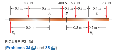
Expert Solution & Answer
Want to see the full answer?
Check out a sample textbook solution
Students have asked these similar questions
Your answer is partially correct.
For the simply supported beam subjected to the loading shown, derive equations for the shear force V and the bending moment M
for any location in the beam. (Place the origin at point A.) Let a=2.50 m, b=4.25 m, Pg= 45kN, and Pc = 90kN. Construct the shear-
force and bending-moment diagrams on paper and use the results to answer the questions in the subsequent parts of this GO
exercise.
Answers:
Ay=
a
74.189
B
Calculate the reaction forces Ay and Dy acting on the beam. Positive values for the reactions are indicated by the directions of the
red arrows shown on the free-body diagram below. (Note: Since Ax = 0, it has been omitted from the free-body diagram.)
Dy= i 59.21
B
a
PB
a
Pc
KN
Pc
b
KN
D
b
D
P
x
In Figure 4a, a beam is supported at A and C with a uniformly distributed load of 20 kN/m between A and B. Draw and label the shear force diagram (SFD) and bending moment diagram (BMD) for the beam shown in Figure Q3a. Label the values for shear force and bending moment at points A, B, C & at the beam mid-point M; the maximum bending moment and its distance from A; and clearly indicate the type of bending between AB and between BC. (show all work)
A thin beam with a solid rectangular cross-section is loaded as shown in Figure Q7 below.
L/3
L/3
L/3
Figure Q7
Consider the following statoments and select which combination correctly describes the bending moment diagram for this beam, along its longth
using the sign conventions provided in lectures.
i lt is symmetrical.
ii It has a value of zero at the mid-point.
i. It has a negative value for the entire length of the beam.
iv. It is described by a quadratic (2nd order) function.
O ali and i. are both correct.
Ob.li. and iv. are both correct.
Oci. and i. are both correct.
Od.i. and iv. are both correct.
Oe. li. and iv. are both correct.
O. None of the provided answers are correct.
OBi and i. are both correct.
Chapter 3 Solutions
Machine Elements in Mechanical Design (6th Edition) (What's New in Trades & Technology)
Ch. 3 - A tensile member in a machine structure is...Ch. 3 - Compute the stress in a round bar having a...Ch. 3 - Compute the stress in a rectangular bar having...Ch. 3 - A link in a packaging machine mechanism has a...Ch. 3 - Two circular rods support the 3800 lb weight of a...Ch. 3 - A tensile load of 5.00 kN is applied to a square...Ch. 3 - An aluminum rod is made in the form of a hollow...Ch. 3 - Compute the stress in the middle portion of rod AC...Ch. 3 - Compute the forces in the two angled rods in...Ch. 3 - If the rods from Problem 9 are circular, determine...
Ch. 3 - Repeat Problems 9 and 10 if the angle is 15 .Ch. 3 - Figure P312 shows a small truss spanning between...Ch. 3 - The truss shown in Figure P313 spans a total space...Ch. 3 - Figure P314 shows a short leg for a machine that...Ch. 3 - Consider the short compression member shown in...Ch. 3 - Refer Figure P38 . Each of the pins at A, B, and C...Ch. 3 - Compute the shear stress in the pins connecting...Ch. 3 - Prob. 18PCh. 3 - Prob. 19PCh. 3 - Prob. 20PCh. 3 - Prob. 21PCh. 3 - Compute the torsional shear stress in a circular...Ch. 3 - If the shaft of Problem 22 is 850 mm long and is...Ch. 3 - Compute the torsional shear stress due to a torque...Ch. 3 - Compute the torsional shear stress in a solid...Ch. 3 - Compute the torsional shear stress in a hollow...Ch. 3 - Compute the angle of twist for the hollow shaft of...Ch. 3 - A square steel bar, 25 mm on a side and 650 mm...Ch. 3 - A 3.00 in-diameter steel bar has a flat milled on...Ch. 3 - A commercial steel supplier lists rectangular...Ch. 3 - A beam is simply supported and carries the load...Ch. 3 - For each beam of Problem 31, compute its weight if...Ch. 3 - For each beam of Problem 31, compute the maximum...Ch. 3 - For the beam loading of Figure P334, draw the...Ch. 3 - For the beam loading of Figure P334, design the...Ch. 3 - Figure P336 shows a beam made from 4 in schedule...Ch. 3 - Select an aluminum I-beam shape to carry the load...Ch. 3 - Figure P338 represents a wood joist for a...Ch. 3 - For Problems 39 through 50, draw the free-body...Ch. 3 - Prob. 40PCh. 3 - For Problems 39 through 50, draw the free-body...Ch. 3 - Prob. 42PCh. 3 - Prob. 43PCh. 3 - Prob. 44PCh. 3 - For Problems 39 through 50, draw the free-body...Ch. 3 - For Problems 39 through 50, draw the free-body...Ch. 3 - For Problems 39 through 50, draw the free-body...Ch. 3 - For Problems 4850, draw the free-body diagram of...Ch. 3 - For Problems 4850, draw the free-body diagram of...Ch. 3 - Prob. 50PCh. 3 - Compute the maximum tensile stress in the bracket...Ch. 3 - Compute the maximum tensile and compressive...Ch. 3 - For the lever shown in Figure P353 (a), compute...Ch. 3 - Compute the maximum tensile stress at sections A...Ch. 3 - Prob. 55PCh. 3 - Refer to Figure P38. Compute the maximum tensile...Ch. 3 - Prob. 57PCh. 3 - Refer to P342. Compute the maximum stress in the...Ch. 3 - Refer to P343. Compute the maximum stress in the...Ch. 3 - Prob. 60PCh. 3 - Figure P361 shows a valve stem from an engine...Ch. 3 - The conveyor fixture shown in Figure P362 carries...Ch. 3 - For the flat plate in tension in Figure P363,...Ch. 3 - For Problems 64 through 68, compute the maximum...Ch. 3 - For Problems 64 through 68, compute the maximum...Ch. 3 - For Problems 64 through 68, compute the maximum...Ch. 3 - For Problems 64 through 68, compute the maximum...Ch. 3 - Prob. 68PCh. 3 - Figure P369 shows a horizontal beam supported by a...Ch. 3 - Prob. 70PCh. 3 - Prob. 71PCh. 3 - The beam shown in Figure P372 is a stepped, flat...Ch. 3 - Figure P373 shows a stepped, flat bar having a...Ch. 3 - Figure P374 shows a bracket carrying opposing...Ch. 3 - Prob. 75PCh. 3 - Figure P376 shows a lever made from a rectangular...Ch. 3 - For the lever in P376, determine the maximum...Ch. 3 - Figure P378 shows a shaft that is loaded only in...Ch. 3 - Prob. 79PCh. 3 - Prob. 80PCh. 3 - A hanger is made from ASTM A36 structural steel...Ch. 3 - A coping saw frame shown in Figure P382 is made...Ch. 3 - Prob. 83PCh. 3 - Figure P384 shows a hand garden tool used to break...Ch. 3 - Figure P385 shows a basketball backboard and goal...Ch. 3 - Prob. 86P
Knowledge Booster


Learn more about
Need a deep-dive on the concept behind this application? Look no further. Learn more about this topic, mechanical-engineering and related others by exploring similar questions and additional content below.Similar questions
- A seesaw weighing 3 lb/ft of length is occupied by two children, each weighing 90 lb (see figure). The center of gravity of each child is 8 ft from the fulcrum. The board is 19 ft long, 8 in. wide, and 1.5 in. thick. What is the maximum bending stress in the board?arrow_forwardFor the simply supported beam subjected to the loading shown, derive equations for the shear force V and the bending moment M for any location in the beam. (Place the origin at point A.) Let a-3.25 m, b=4.75 m, Pg = 35kN, and Pc = 80kN. Construct the shear- force and bending-moment diagrams on paper and use the results to answer the questions in the subsequent parts of this GO exercise. Answers: Ay= Dy = a M. B a PB Calculate the reaction forces Ay and Dy acting on the beam. Positive values for the reactions are indicated by the directions of the red arrows shown on the free-body diagram below. (Note: Since Ax = 0, it has been omitted from the free-body diagram.) PB Pc a Pc kN b KN D b D X D Xarrow_forwardProblem 2 (a) Please compute and plot the shear force and bending moment diagrams for the beam shown below in Figure 2.1. Please use the method of sections to get the equations for shear force and bending moment, and use a computer to plot the diagrams and get the maximum value of bending moment. (b) For beam in problem 2-(a), suggest the lightest-weight wide-flange beam (use Appendix B) made of A-36 Structural Steel that avoids yielding with a factor of safety of at least 2. Use Sy (σy)=250 MPa. 50 kN/m Hinge 3@2m 6m = Figure 2.1arrow_forward
- Consider the beam shown in (Figure 1). Suppose that the distributed load intensities w1 = 60 lb/ft and w2 = 40 lb/ft . Follow the sign convention. Determine the internal normal force, shear force and moment at point C. Determine the internal normal force, shear force and moment at point D.arrow_forwardFigure shows a composite beam having a symmetry trapezium cross-section compromised of steel and brass being subjected to bending moment. Using the data given in Table, and factor of safety of 3.5, determine the largest bending moment M which can be applied to the composite beam when it is being bent about x-axis.arrow_forwardIn Figure Q3a, a beam is supported at A and C with a uniformly distributed load of20 kN/m between A and B. Draw and label the shear force diagram (SFD) andbending moment diagram (BMD) for the beam shown in Figure Q3a. Label thevalues for shear force and bending moment at points A, B, C & at the beam midpoint M; the maximum bending moment and its distance from A; and clearlyindicate the type of bending between AB and between BCarrow_forward
- Use Singularity functions to draw the shear and bending moment diagram for this beam problem in terms of F and L.arrow_forwardIf the shape in problem 5 is used for a beam with Mmax = 25 k-ft, what is the maximum bending stress?arrow_forwardFor the cantilever beam shown in the figure below, invoke the equilibrium of cut free-body sections of the beam to (a) write equations for the shear force and bending moment distributions as functions of x. Include a free-body diagram of each cut section and force and moment balance calculations. Examine the shear force and bending moment formulas and deduce the sign of the deformation within each inter- val. Include a sketch of a deformed material element that illustrates the shear and bending deformation within the interval. (b) Find the shear force of the largest magnitude in the beam and state where it occurs within the beam. (c) Find the bending moment of the largest magnitude in the beam and state where it occurs within the beam. 200 N/m 0.6 m- X 600 N 0.2 m 0.2 marrow_forward
- In Figure Q5b, a beam is supported at A and C with a uniformly distributed load (UDL) of 38.75 kN/m between A and B. Distance L1 = 9.00 m and L2 = 4.50 m. Draw and label the shear force diagram (SFD) and bending moment diagram (BMD) for the beam shown in Figure Q5b. Label the shear force and the bending moment values at points A, B & C on both diagrams; determine the distance from A along the beam where the shear force is zero; and calculate the bending moment at the point where the shear force is zero. Clearly indicate the type of bending between AC and between BC. A UDL L1 Figure Q5b B L2 Carrow_forward(a) derive equations for the shear force V and the bending momentM for any location in the beam. (Place the origin at point A.)(b) use the derived functions to plot the shear-force and bendingmomentdiagrams for the beam.(c) specify the values for key points on the diagrams.arrow_forwardThe bending moment Mx affects the cross section of the beam given in Figure 4. Beam cross section Calculation of normal stress at points 1,2,3 and normal Plot the stress distribution. a (mm)=255 b (mm)=40 c (mm)=230 d (mm)=50 Mx (kNm)= 53arrow_forward
arrow_back_ios
SEE MORE QUESTIONS
arrow_forward_ios
Recommended textbooks for you
 Mechanics of Materials (MindTap Course List)Mechanical EngineeringISBN:9781337093347Author:Barry J. Goodno, James M. GerePublisher:Cengage Learning
Mechanics of Materials (MindTap Course List)
Mechanical Engineering
ISBN:9781337093347
Author:Barry J. Goodno, James M. Gere
Publisher:Cengage Learning
Solids: Lesson 53 - Slope and Deflection of Beams Intro; Author: Jeff Hanson;https://www.youtube.com/watch?v=I7lTq68JRmY;License: Standard YouTube License, CC-BY