
Machine Elements in Mechanical Design (6th Edition) (What's New in Trades & Technology)
6th Edition
ISBN: 9780134441184
Author: Robert L. Mott, Edward M. Vavrek, Jyhwen Wang
Publisher: PEARSON
expand_more
expand_more
format_list_bulleted
Videos
Textbook Question
Chapter 3, Problem 62P
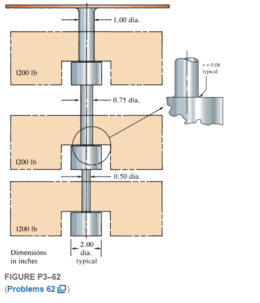
The conveyor fixture shown in Figure P3−62 carries three heavy assemblies (1200 lb each). Compute the maximum stress in the fixture, considering stress concentrations at the fillets and assuming that the load acts axially.
Expert Solution & Answer
Want to see the full answer?
Check out a sample textbook solution
Students have asked these similar questions
Solve for the load in each member of the system in the figure.
The figure below is a schematic drawing of a shaft that supports two V-belt pulleys. The loose belt tension on the pulley at A is 15% of the tension on the tight side. The shaft material has a yield strength of 300 MPa and an ultimate tensile strength of 520 MPa. Calculate the shaft diameter.
Compute the forces in the two angled rods in Figure below for an applied force, F = 1500 lb, if the angle u is 45°.
Chapter 3 Solutions
Machine Elements in Mechanical Design (6th Edition) (What's New in Trades & Technology)
Ch. 3 - A tensile member in a machine structure is...Ch. 3 - Compute the stress in a round bar having a...Ch. 3 - Compute the stress in a rectangular bar having...Ch. 3 - A link in a packaging machine mechanism has a...Ch. 3 - Two circular rods support the 3800 lb weight of a...Ch. 3 - A tensile load of 5.00 kN is applied to a square...Ch. 3 - An aluminum rod is made in the form of a hollow...Ch. 3 - Compute the stress in the middle portion of rod AC...Ch. 3 - Compute the forces in the two angled rods in...Ch. 3 - If the rods from Problem 9 are circular, determine...
Ch. 3 - Repeat Problems 9 and 10 if the angle is 15 .Ch. 3 - Figure P312 shows a small truss spanning between...Ch. 3 - The truss shown in Figure P313 spans a total space...Ch. 3 - Figure P314 shows a short leg for a machine that...Ch. 3 - Consider the short compression member shown in...Ch. 3 - Refer Figure P38 . Each of the pins at A, B, and C...Ch. 3 - Compute the shear stress in the pins connecting...Ch. 3 - Prob. 18PCh. 3 - Prob. 19PCh. 3 - Prob. 20PCh. 3 - Prob. 21PCh. 3 - Compute the torsional shear stress in a circular...Ch. 3 - If the shaft of Problem 22 is 850 mm long and is...Ch. 3 - Compute the torsional shear stress due to a torque...Ch. 3 - Compute the torsional shear stress in a solid...Ch. 3 - Compute the torsional shear stress in a hollow...Ch. 3 - Compute the angle of twist for the hollow shaft of...Ch. 3 - A square steel bar, 25 mm on a side and 650 mm...Ch. 3 - A 3.00 in-diameter steel bar has a flat milled on...Ch. 3 - A commercial steel supplier lists rectangular...Ch. 3 - A beam is simply supported and carries the load...Ch. 3 - For each beam of Problem 31, compute its weight if...Ch. 3 - For each beam of Problem 31, compute the maximum...Ch. 3 - For the beam loading of Figure P334, draw the...Ch. 3 - For the beam loading of Figure P334, design the...Ch. 3 - Figure P336 shows a beam made from 4 in schedule...Ch. 3 - Select an aluminum I-beam shape to carry the load...Ch. 3 - Figure P338 represents a wood joist for a...Ch. 3 - For Problems 39 through 50, draw the free-body...Ch. 3 - Prob. 40PCh. 3 - For Problems 39 through 50, draw the free-body...Ch. 3 - Prob. 42PCh. 3 - Prob. 43PCh. 3 - Prob. 44PCh. 3 - For Problems 39 through 50, draw the free-body...Ch. 3 - For Problems 39 through 50, draw the free-body...Ch. 3 - For Problems 39 through 50, draw the free-body...Ch. 3 - For Problems 4850, draw the free-body diagram of...Ch. 3 - For Problems 4850, draw the free-body diagram of...Ch. 3 - Prob. 50PCh. 3 - Compute the maximum tensile stress in the bracket...Ch. 3 - Compute the maximum tensile and compressive...Ch. 3 - For the lever shown in Figure P353 (a), compute...Ch. 3 - Compute the maximum tensile stress at sections A...Ch. 3 - Prob. 55PCh. 3 - Refer to Figure P38. Compute the maximum tensile...Ch. 3 - Prob. 57PCh. 3 - Refer to P342. Compute the maximum stress in the...Ch. 3 - Refer to P343. Compute the maximum stress in the...Ch. 3 - Prob. 60PCh. 3 - Figure P361 shows a valve stem from an engine...Ch. 3 - The conveyor fixture shown in Figure P362 carries...Ch. 3 - For the flat plate in tension in Figure P363,...Ch. 3 - For Problems 64 through 68, compute the maximum...Ch. 3 - For Problems 64 through 68, compute the maximum...Ch. 3 - For Problems 64 through 68, compute the maximum...Ch. 3 - For Problems 64 through 68, compute the maximum...Ch. 3 - Prob. 68PCh. 3 - Figure P369 shows a horizontal beam supported by a...Ch. 3 - Prob. 70PCh. 3 - Prob. 71PCh. 3 - The beam shown in Figure P372 is a stepped, flat...Ch. 3 - Figure P373 shows a stepped, flat bar having a...Ch. 3 - Figure P374 shows a bracket carrying opposing...Ch. 3 - Prob. 75PCh. 3 - Figure P376 shows a lever made from a rectangular...Ch. 3 - For the lever in P376, determine the maximum...Ch. 3 - Figure P378 shows a shaft that is loaded only in...Ch. 3 - Prob. 79PCh. 3 - Prob. 80PCh. 3 - A hanger is made from ASTM A36 structural steel...Ch. 3 - A coping saw frame shown in Figure P382 is made...Ch. 3 - Prob. 83PCh. 3 - Figure P384 shows a hand garden tool used to break...Ch. 3 - Figure P385 shows a basketball backboard and goal...Ch. 3 - Prob. 86P
Knowledge Booster


Learn more about
Need a deep-dive on the concept behind this application? Look no further. Learn more about this topic, mechanical-engineering and related others by exploring similar questions and additional content below.Similar questions
- Repeat Problem 11.2-3 assuming that R= 10 kN · m/rad and L = 2 m.arrow_forwardA cable and pulley system in the figure part a supports a cage of a mass 300 kg at B. Assume that this includes the mass of the cables as well. The thickness or each of the three steel pulleys is t = 40 mm. The pin diameters are dPA= 25 mm, dB= 30 mm. and dc= 22 mm (see figure part a and part b). (a) Find expressions for the resultant forces acting on the pulleys at A, B. and C in terms of cubic tension T. (b) What is the maximum weight W that can be added to the cage at B based on the following allowable stresses? Shear stress in the pins is 50 MPa; bearing stress between the pin and the pulley is 110 MPa.arrow_forwardRepeat Problem 11.3-9. Use two C 150 × 12.2 steel shapes and assume that E = 205 GPa and L = 6 m.arrow_forward
- Repeat Problem 10.4-41 for the loading shown in the figure.arrow_forwardRepeat Problem 2.3-29 if vertical load P at D is replaced by a horizontal load P at D (see figure).arrow_forwarda b c d h 82 mm 139 mm 39 mm 18 mm 33 mm Clamps like the one shown are commonly used in woodworking applications. This clamp has the dimensions given above, and its jaws are 38 mm wide (in the direction perpendicular to the plane of the picture). The screws of the clamp are adjusted so that there is a uniform pressure of 190 kPa being applied to the workpieces by the jaws. Find the force carried in each screw.Note: Assume that A, B, C, and D act as pins. (Denote tension forces with positive values; compressive forces with negative values.)arrow_forward
- For problem on the picture. assume that the left side of the spring has a fixed end and the other side has pull force applied to it. The force applied to the spring is 3lbf. Solve for the following:a. Draw the free body diagram using the equivalent spring constantb. total deformation of the springarrow_forward3-67: A short post is made by welding steel plates into a square. as shown in Figure P3-67, and then filling the area inside with concrete. Compute the stress in the steel and in the concrete if b = 1500 mm and t = 10mm, and the post carries an axial load of 900 kN. See Section 2-10 for concrete properties. Use f'c = 6000 psi.arrow_forward4- 3 cables with same diameter are used to hold the plate. Calculate the tensile loads in all cables if the load P is applied to the center of the plate. Carrow_forward
- Compute the stresses at A and B on the link loaded as shown in Figure P-912 if P = 9000 lb and F = 3000 lb.arrow_forwardSituation 4 - A load of W = 30 L1 L2 kN is lifted through a boom BCD as shown in the Figure a AP-4.10. The boom makes an angle of 60° with the vertical. Neglect the weight of the boom and for this w problem, L1 = L2 = 2 m. The pulley at D is frictionless. 10. Determine the angle a. 60° Answer: 30° 11. What is the tension in cable Figure AP-4.10 B. AC in kN? Answer: 25.36 kN 12. What is the total reaction at B in kN? Answer: 54.77 kNarrow_forwardIn the figure below, all the bearings are movable bearings and the C bearing is in an inclined position. Draw the M, N, T diagrams according to your force values. (20kN force is perpendicular to the beam it acts on. P1, P2, P3 forces are in the vertical direction.) q=7 kN/m P1=25 kN P2=27 kN P3=11 kNarrow_forward
arrow_back_ios
SEE MORE QUESTIONS
arrow_forward_ios
Recommended textbooks for you
 Mechanics of Materials (MindTap Course List)Mechanical EngineeringISBN:9781337093347Author:Barry J. Goodno, James M. GerePublisher:Cengage Learning
Mechanics of Materials (MindTap Course List)
Mechanical Engineering
ISBN:9781337093347
Author:Barry J. Goodno, James M. Gere
Publisher:Cengage Learning
Mechanical SPRING DESIGN Strategy and Restrictions in Under 15 Minutes!; Author: Less Boring Lectures;https://www.youtube.com/watch?v=dsWQrzfQt3s;License: Standard Youtube License