
Machine Elements in Mechanical Design (6th Edition) (What's New in Trades & Technology)
6th Edition
ISBN: 9780134441184
Author: Robert L. Mott, Edward M. Vavrek, Jyhwen Wang
Publisher: PEARSON
expand_more
expand_more
format_list_bulleted
Concept explainers
Videos
Textbook Question
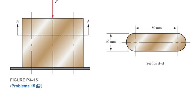
Chapter 3, Problem 15P
Consider the short compression member shown in Figure P3−15. Compute the compressive stress if the cross section has the shape shown and the applied load is 640 kN.
Expert Solution & Answer
Want to see the full answer?
Check out a sample textbook solution
Students have asked these similar questions
A 120 mm ×100 mm ×20 mm T section is used as a simply supported beam. The beam carries the applied eccentric load F of 120 KN at the position indicated in the Figure Q5. Start your calculations be setting an origin from the right most point on the cross section and determine the following :
5.1.The maximum compressive and tensile longitudinal direct stresses induced in the column.
5.2. Plot the stress distribution diagram and determine the position of the NA
3. A rectangular solid bar of width 20mm and depth 35mm is
subject to a pure positive moment of 450Nm. Calculate the
stress in the bar and sketch the stress distribution
through its thickness along the centre line.
4. The bar in Q3 is also subject to a tensile load of 15kN
applied at the centroid of area. Calculate the stress in
the bar and sketch the stress distribution through its
thickness along the centre line.
The figure below shows a simply supported prismatic beam with an applied uniform load. The labeled points A through E are equally spaced (at the quarter points) along the length of the beam and are located at the top of the beam section. Points A and E may be assumed to be located directly above the supports. Rank the points, from greatest to least, on the basis of the absolute value of normal stress in the beam section.
Chapter 3 Solutions
Machine Elements in Mechanical Design (6th Edition) (What's New in Trades & Technology)
Ch. 3 - A tensile member in a machine structure is...Ch. 3 - Compute the stress in a round bar having a...Ch. 3 - Compute the stress in a rectangular bar having...Ch. 3 - A link in a packaging machine mechanism has a...Ch. 3 - Two circular rods support the 3800 lb weight of a...Ch. 3 - A tensile load of 5.00 kN is applied to a square...Ch. 3 - An aluminum rod is made in the form of a hollow...Ch. 3 - Compute the stress in the middle portion of rod AC...Ch. 3 - Compute the forces in the two angled rods in...Ch. 3 - If the rods from Problem 9 are circular, determine...
Ch. 3 - Repeat Problems 9 and 10 if the angle is 15 .Ch. 3 - Figure P312 shows a small truss spanning between...Ch. 3 - The truss shown in Figure P313 spans a total space...Ch. 3 - Figure P314 shows a short leg for a machine that...Ch. 3 - Consider the short compression member shown in...Ch. 3 - Refer Figure P38 . Each of the pins at A, B, and C...Ch. 3 - Compute the shear stress in the pins connecting...Ch. 3 - Prob. 18PCh. 3 - Prob. 19PCh. 3 - Prob. 20PCh. 3 - Prob. 21PCh. 3 - Compute the torsional shear stress in a circular...Ch. 3 - If the shaft of Problem 22 is 850 mm long and is...Ch. 3 - Compute the torsional shear stress due to a torque...Ch. 3 - Compute the torsional shear stress in a solid...Ch. 3 - Compute the torsional shear stress in a hollow...Ch. 3 - Compute the angle of twist for the hollow shaft of...Ch. 3 - A square steel bar, 25 mm on a side and 650 mm...Ch. 3 - A 3.00 in-diameter steel bar has a flat milled on...Ch. 3 - A commercial steel supplier lists rectangular...Ch. 3 - A beam is simply supported and carries the load...Ch. 3 - For each beam of Problem 31, compute its weight if...Ch. 3 - For each beam of Problem 31, compute the maximum...Ch. 3 - For the beam loading of Figure P334, draw the...Ch. 3 - For the beam loading of Figure P334, design the...Ch. 3 - Figure P336 shows a beam made from 4 in schedule...Ch. 3 - Select an aluminum I-beam shape to carry the load...Ch. 3 - Figure P338 represents a wood joist for a...Ch. 3 - For Problems 39 through 50, draw the free-body...Ch. 3 - Prob. 40PCh. 3 - For Problems 39 through 50, draw the free-body...Ch. 3 - Prob. 42PCh. 3 - Prob. 43PCh. 3 - Prob. 44PCh. 3 - For Problems 39 through 50, draw the free-body...Ch. 3 - For Problems 39 through 50, draw the free-body...Ch. 3 - For Problems 39 through 50, draw the free-body...Ch. 3 - For Problems 4850, draw the free-body diagram of...Ch. 3 - For Problems 4850, draw the free-body diagram of...Ch. 3 - Prob. 50PCh. 3 - Compute the maximum tensile stress in the bracket...Ch. 3 - Compute the maximum tensile and compressive...Ch. 3 - For the lever shown in Figure P353 (a), compute...Ch. 3 - Compute the maximum tensile stress at sections A...Ch. 3 - Prob. 55PCh. 3 - Refer to Figure P38. Compute the maximum tensile...Ch. 3 - Prob. 57PCh. 3 - Refer to P342. Compute the maximum stress in the...Ch. 3 - Refer to P343. Compute the maximum stress in the...Ch. 3 - Prob. 60PCh. 3 - Figure P361 shows a valve stem from an engine...Ch. 3 - The conveyor fixture shown in Figure P362 carries...Ch. 3 - For the flat plate in tension in Figure P363,...Ch. 3 - For Problems 64 through 68, compute the maximum...Ch. 3 - For Problems 64 through 68, compute the maximum...Ch. 3 - For Problems 64 through 68, compute the maximum...Ch. 3 - For Problems 64 through 68, compute the maximum...Ch. 3 - Prob. 68PCh. 3 - Figure P369 shows a horizontal beam supported by a...Ch. 3 - Prob. 70PCh. 3 - Prob. 71PCh. 3 - The beam shown in Figure P372 is a stepped, flat...Ch. 3 - Figure P373 shows a stepped, flat bar having a...Ch. 3 - Figure P374 shows a bracket carrying opposing...Ch. 3 - Prob. 75PCh. 3 - Figure P376 shows a lever made from a rectangular...Ch. 3 - For the lever in P376, determine the maximum...Ch. 3 - Figure P378 shows a shaft that is loaded only in...Ch. 3 - Prob. 79PCh. 3 - Prob. 80PCh. 3 - A hanger is made from ASTM A36 structural steel...Ch. 3 - A coping saw frame shown in Figure P382 is made...Ch. 3 - Prob. 83PCh. 3 - Figure P384 shows a hand garden tool used to break...Ch. 3 - Figure P385 shows a basketball backboard and goal...Ch. 3 - Prob. 86P
Knowledge Booster


Learn more about
Need a deep-dive on the concept behind this application? Look no further. Learn more about this topic, mechanical-engineering and related others by exploring similar questions and additional content below.Similar questions
- Solve the preceding problem if F =90 mm, F = 42 kN, and t = 40°MPaarrow_forwardA flat bar of width b and thickness t has a hole of diameter d drilled through it (see figure). The hole may have any diameter that will fit within the bar. What is the maximum permissible tensile load Pmaxif the allowable tensile stress in the material is st?arrow_forwardRepeat Problem 11.3-9. Use two C 150 × 12.2 steel shapes and assume that E = 205 GPa and L = 6 m.arrow_forward
- A rod of different materials is arranged as shown with the corresponding axial forces (see figure 3). Find the maximum value of the force P in kN such that it will not exceed a stress in steel of 140,000 kPa, in aluminum of 90,000 kPa, or in bronze of 100,000 kPa. INPUT THE NUMERICAL VALUE ONLY IN 3 DECIMAL PLACESarrow_forwardWrite the solution for the following: Member BC= 600 N Member FG = -600 Narrow_forwardThe figure shows the free body diagram of a connecting link portion having stress concentration at three sections. If the yield strength is 3.8MPa, find the dimensions using factor of safety of 2.5.arrow_forward
- A square tie bar 20 mm x 20 mm in section carries a load. It is attached to a bracket by means of 6 bolts. Calculate the diameter of the bolt if the maximum stress in the tie bar is 150 N/mm2 and in the bolts is 75 N/mm2.arrow_forward6.14 Determine the nodal displacements and the element stresses, including prin- cipal stresses, due to the loads shown for the thin plates in Figure P6-14. Use E = 105 GPa, v=0.30, and r = 5 mm. Assume plane stress conditions apply. The recommended discretized plates are shown in the figures. Use a computer program to solve these. 400 mm Xt 400 mm 30 kN Figure P6-14 (c)arrow_forwardThe column shown in Figure B-1(a), not drawn to scale, carries a horizontal load W applied in the plane of the web; the cross-section of the column is shown in Figure B-1 (b). If the maximum value of direct stress in the column is limited to +-155 N/mm2 calculate the maximum allowable value of W. (For a rectangular section, I=bh3/12; Parallel axis theorem IX=Ix+Ad2arrow_forward
- Figure Q5 shows a thick cylinder of 50 mm internal radius and 130 mm outer radius is subjected to an internal pressure of 60 MN/m2 and an external pressure of 30 MN/m2. Determine the hoop and radial stresses at the inside and outside of the cylinder together with the longitudinal stress if the cylinder is assumed to have closed ends using analytical and graphical approachesarrow_forwardA 28 mm diameter rod with a 30 mm diameter handle as shown in Figure Q1 has two 90 degree bends. The handle is attached to the wall at 'A' while 1.8kN load is applied at the end of the rod at 'E'. Calculate Maximum Shear Stress at location 'A' and 'B' and determine it critical location. Bending load at point 'A'? Bending load at point 'B'? (Nm) Torsion load at rod; 'T'? Normal Stress due to bending load at point 'A'? (MPashear Stress due to torsion load at point 'A'? (MPa) 1st Principle stress at point 'A' (max principle stress)? (MPa Maximum shear stress at point 'B'? Critical Location? (L1) 170 $30- (L2) в 470 $28- F= 1.8kN| E 300 100 (L3) D Figure Q1arrow_forwardTwo circular rods of 50 mm diameter are connected by a knuckle joint, as shown in Figure 1, by a pin of 40 mm in diameter. If a pull of 120 kN acts at each end, find the tensile stress in the rod and shear stress in the pin.arrow_forward
arrow_back_ios
SEE MORE QUESTIONS
arrow_forward_ios
Recommended textbooks for you
 Mechanics of Materials (MindTap Course List)Mechanical EngineeringISBN:9781337093347Author:Barry J. Goodno, James M. GerePublisher:Cengage Learning
Mechanics of Materials (MindTap Course List)
Mechanical Engineering
ISBN:9781337093347
Author:Barry J. Goodno, James M. Gere
Publisher:Cengage Learning
Everything About COMBINED LOADING in 10 Minutes! Mechanics of Materials; Author: Less Boring Lectures;https://www.youtube.com/watch?v=N-PlI900hSg;License: Standard youtube license