
Machine Elements in Mechanical Design (6th Edition) (What's New in Trades & Technology)
6th Edition
ISBN: 9780134441184
Author: Robert L. Mott, Edward M. Vavrek, Jyhwen Wang
Publisher: PEARSON
expand_more
expand_more
format_list_bulleted
Concept explainers
Videos
Textbook Question
Chapter 3, Problem 13P
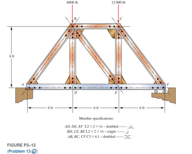
The truss shown in Figure P3−13 spans a total space of 18.0 ft and carries two concentrated loads on its top chord. The members are made from standard steel angle and channel shapes as indicated in the figure. Consider all joints to be pinned. Compute the stresses in all members near their midpoints away from the connections.
Expert Solution & Answer
Want to see the full answer?
Check out a sample textbook solution
Students have asked these similar questions
The figure shows a roof truss and the detail of connection at joint I. The allowable stresses are 70 MPa for shear and 120 MPa for bearing. How many 20-mm diameter rivets are required to fasten member IG to the gusset plate? What is the required area for member AI if the allowable axial stress is 180 MPa.
Answer Problem 6-22 from P. 271 of your textbook and the additional questions below, assuming the stress in cable AB is within the proportional limit. Include a carefully labelled free-body diagram for the pipe strut as part of your solution. Show all work.
The figure shows a flat hanger bar for supporting shop equipment in a factory. The bar is fixed to a support by means of a bolted connection. The main part of the hanging bar is 1.5 inches wide. This width varies up to 3.0 inches. A 1.0-inch diameter bolt transfers the hanger bar load to the two top bracket plates.
Determine the allowable stress of the tension load P in the hanger in the following two instances:
to. The allowable tensile stress in the main part of the hanger is 16,000 psi.
b. The allowable stress load between the hanger bar and the bolt is 26,000 lb/pu.
Chapter 3 Solutions
Machine Elements in Mechanical Design (6th Edition) (What's New in Trades & Technology)
Ch. 3 - A tensile member in a machine structure is...Ch. 3 - Compute the stress in a round bar having a...Ch. 3 - Compute the stress in a rectangular bar having...Ch. 3 - A link in a packaging machine mechanism has a...Ch. 3 - Two circular rods support the 3800 lb weight of a...Ch. 3 - A tensile load of 5.00 kN is applied to a square...Ch. 3 - An aluminum rod is made in the form of a hollow...Ch. 3 - Compute the stress in the middle portion of rod AC...Ch. 3 - Compute the forces in the two angled rods in...Ch. 3 - If the rods from Problem 9 are circular, determine...
Ch. 3 - Repeat Problems 9 and 10 if the angle is 15 .Ch. 3 - Figure P312 shows a small truss spanning between...Ch. 3 - The truss shown in Figure P313 spans a total space...Ch. 3 - Figure P314 shows a short leg for a machine that...Ch. 3 - Consider the short compression member shown in...Ch. 3 - Refer Figure P38 . Each of the pins at A, B, and C...Ch. 3 - Compute the shear stress in the pins connecting...Ch. 3 - Prob. 18PCh. 3 - Prob. 19PCh. 3 - Prob. 20PCh. 3 - Prob. 21PCh. 3 - Compute the torsional shear stress in a circular...Ch. 3 - If the shaft of Problem 22 is 850 mm long and is...Ch. 3 - Compute the torsional shear stress due to a torque...Ch. 3 - Compute the torsional shear stress in a solid...Ch. 3 - Compute the torsional shear stress in a hollow...Ch. 3 - Compute the angle of twist for the hollow shaft of...Ch. 3 - A square steel bar, 25 mm on a side and 650 mm...Ch. 3 - A 3.00 in-diameter steel bar has a flat milled on...Ch. 3 - A commercial steel supplier lists rectangular...Ch. 3 - A beam is simply supported and carries the load...Ch. 3 - For each beam of Problem 31, compute its weight if...Ch. 3 - For each beam of Problem 31, compute the maximum...Ch. 3 - For the beam loading of Figure P334, draw the...Ch. 3 - For the beam loading of Figure P334, design the...Ch. 3 - Figure P336 shows a beam made from 4 in schedule...Ch. 3 - Select an aluminum I-beam shape to carry the load...Ch. 3 - Figure P338 represents a wood joist for a...Ch. 3 - For Problems 39 through 50, draw the free-body...Ch. 3 - Prob. 40PCh. 3 - For Problems 39 through 50, draw the free-body...Ch. 3 - Prob. 42PCh. 3 - Prob. 43PCh. 3 - Prob. 44PCh. 3 - For Problems 39 through 50, draw the free-body...Ch. 3 - For Problems 39 through 50, draw the free-body...Ch. 3 - For Problems 39 through 50, draw the free-body...Ch. 3 - For Problems 4850, draw the free-body diagram of...Ch. 3 - For Problems 4850, draw the free-body diagram of...Ch. 3 - Prob. 50PCh. 3 - Compute the maximum tensile stress in the bracket...Ch. 3 - Compute the maximum tensile and compressive...Ch. 3 - For the lever shown in Figure P353 (a), compute...Ch. 3 - Compute the maximum tensile stress at sections A...Ch. 3 - Prob. 55PCh. 3 - Refer to Figure P38. Compute the maximum tensile...Ch. 3 - Prob. 57PCh. 3 - Refer to P342. Compute the maximum stress in the...Ch. 3 - Refer to P343. Compute the maximum stress in the...Ch. 3 - Prob. 60PCh. 3 - Figure P361 shows a valve stem from an engine...Ch. 3 - The conveyor fixture shown in Figure P362 carries...Ch. 3 - For the flat plate in tension in Figure P363,...Ch. 3 - For Problems 64 through 68, compute the maximum...Ch. 3 - For Problems 64 through 68, compute the maximum...Ch. 3 - For Problems 64 through 68, compute the maximum...Ch. 3 - For Problems 64 through 68, compute the maximum...Ch. 3 - Prob. 68PCh. 3 - Figure P369 shows a horizontal beam supported by a...Ch. 3 - Prob. 70PCh. 3 - Prob. 71PCh. 3 - The beam shown in Figure P372 is a stepped, flat...Ch. 3 - Figure P373 shows a stepped, flat bar having a...Ch. 3 - Figure P374 shows a bracket carrying opposing...Ch. 3 - Prob. 75PCh. 3 - Figure P376 shows a lever made from a rectangular...Ch. 3 - For the lever in P376, determine the maximum...Ch. 3 - Figure P378 shows a shaft that is loaded only in...Ch. 3 - Prob. 79PCh. 3 - Prob. 80PCh. 3 - A hanger is made from ASTM A36 structural steel...Ch. 3 - A coping saw frame shown in Figure P382 is made...Ch. 3 - Prob. 83PCh. 3 - Figure P384 shows a hand garden tool used to break...Ch. 3 - Figure P385 shows a basketball backboard and goal...Ch. 3 - Prob. 86P
Knowledge Booster


Learn more about
Need a deep-dive on the concept behind this application? Look no further. Learn more about this topic, mechanical-engineering and related others by exploring similar questions and additional content below.Similar questions
- compute the forces in all members and the stresses in the midsection, away from any joint. Refer to the Appendix for the cross-sectional area of the members indicated in the figures. Consider all joints to be pinned 30 2.0 m 2.0 m 10.5 kN (a) 5 mm 30 mm typical 12 mm 10 mm 10 mm 30 mm (c) (d) (b)arrow_forward3) Calculate the internal forces in members DF, CE, and BD of the given truss shown in the figure below. Use the Method of Sections. G0ON GOON GOON GOON G0ON 1,5m 600 N B. 600 N A 6 at 1-20m = 7.20marrow_forwardusing the method of sections , analyse the truss shown in figure 8 below reguarding forces in menbers ED , DF AND FC .arrow_forward
- PROBLEM 1: Compute for the force in each member of the truss shown in FIGURE 1. Indicate in your solutions if the force is in tension or in compression. FIGURE 1 Height of truss= 0.75 Length of horizontal members= 1.00 60 kN B F 25 kN How many members does the truss have? How many support reactions does the truss have? How many joints does the truss have? Considering the number of supports, joints, and members this truss has, this truss is considered What are the force in member: АВ, ВС, CD, AE, ВЕ, СЕ, ЕF, CF, DFarrow_forwardA small seat angle is used to support a beam with a reaction of 6,000 lbs. Two 1/2 inchdiameter bolts are used to resist the load. Compute the stress in each bolt. I'm having a hard time with this problem can you help?arrow_forwardPin jointed frame is subjected to the external loads of F6 = 2733 N at D and F7= 1938 N at C as shown in Figure T2. Take the length of frames indicated as: L6 = 2964 mm and L7= 6164 mm.(i). Draw the free body diagram of the given Frame/Truss;(ii). Estimate the support reactions;(iii). Determine the forces in all members indicating the nature of forces; (iv). Verify the forces in members AD and AE by another suitable method.arrow_forward
- 4. Figure P-130 shows a roof truss and the detail of the riveted connection at joint B. Using allowable stresses of t = 80 MPa and O= 120 MPa, how many 20 - mm diameter rivets are required to fasten member BC to the gusset plate? Member BE? What is the largest average tensile or compressive stress in BC and BE? 14 mm gusser plate 6 m 4 m 4 m 4 m 4 m 75x 75 x 13 mm 96 kN 200 kN 96 kN 75 x 75 x 6 mm Figure P-130 and P-131arrow_forwardThe structure shown below is hinged to fixed supports at A and C. The bars are each 4 in. by 4 in. in section. Compute the maximum tensile stress developed in bar CB assuming the pin connections at A, B, and C are frictionless. 800 lb 5 ft 5 ft C 500 lb 8 ft 6 ft 2 ft -arrow_forwardA truss is subjected to a 10 Kips of vertical load at G, a 30 Kips of vertical load at F and a 10 Kips of vertical load at E as shown in the figure. Calculate: (a) Forces in members AG and AB using the method of joints, (b) Forces in members FC and FE using the method of sections. Show all your calculations. This question can be answered only with a file attachment. Use only A SINGLE PDF file for your answer. Multiple file attachments are not accepted. 10 kips 30 kips 10 kips 10 ft 10 ft 5 ft 15 ft 5 ft 10 ft 10 ft 10 ftarrow_forward
- The column shown in Figure B-1(a), not drawn to scale, carries a horizontal load W applied in the plane of the web; the cross-section of the column is shown in Figure B-1 (b). If the maximum value of direct stress in the column is limited to +-155 N/mm2 calculate the maximum allowable value of W. (For a rectangular section, I=bh3/12; Parallel axis theorem IX=Ix+Ad2arrow_forward3. Calculate the bearing stress and shear stress between the pin and each bracket of a clevis joint. Assume pin diameter of 10 mm, 40 mm wide gap link, 12 mm thick bracket, and 3550N tensile load. Draw a free body diagram (geometry & forces) Identify stress plane Calculate stress and write it (with appropriate units) in the outlined boxarrow_forwardA truss is subjected to a 12 Kips of vertical load at G, a 42 Kips of vertical load at F and a 18 Kips of vertical load at E as shown in the figure. Calculate: (a) Forces in members AG and AB using the method of joints, (show all your calculations) (b) Forces in members FC and FE using the method of sections, (show all your calculations) NOTE: This question can be answered only with a file attachment. Use only A SINGLE PDF file for your answers. DO NOT USE Multiple file attachments. 12 Кіps 42 Kips 18 Kips 10 ft 10 ft 5 ft, 5 ft 15 ft 10 ft B 10 ft 10 ftarrow_forward
arrow_back_ios
SEE MORE QUESTIONS
arrow_forward_ios
Recommended textbooks for you
 Mechanics of Materials (MindTap Course List)Mechanical EngineeringISBN:9781337093347Author:Barry J. Goodno, James M. GerePublisher:Cengage Learning
Mechanics of Materials (MindTap Course List)
Mechanical Engineering
ISBN:9781337093347
Author:Barry J. Goodno, James M. Gere
Publisher:Cengage Learning
Everything About COMBINED LOADING in 10 Minutes! Mechanics of Materials; Author: Less Boring Lectures;https://www.youtube.com/watch?v=N-PlI900hSg;License: Standard youtube license