
Machine Elements in Mechanical Design (6th Edition) (What's New in Trades & Technology)
6th Edition
ISBN: 9780134441184
Author: Robert L. Mott, Edward M. Vavrek, Jyhwen Wang
Publisher: PEARSON
expand_more
expand_more
format_list_bulleted
Concept explainers
Videos
Textbook Question
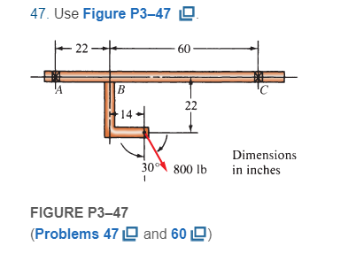
Chapter 3, Problem 47P
For Problems 39 through 50, draw the free-body diagram of only the horizontal beam portion of the given figures. Then draw the complete shear and bending moment diagrams. Where used, the symbol X indicates a simple support capable of exerting a reaction force in any direction but having no moment resistance. For beams having unbalanced axial loads, you may specify which support offers the reaction.
Expert Solution & Answer
Want to see the full answer?
Check out a sample textbook solution
Students have asked these similar questions
In Figure 4a, a beam is supported at A and C with a uniformly distributed load of 20 kN/m between A and B. Draw and label the shear force diagram (SFD) and bending moment diagram (BMD) for the beam shown in Figure Q3a. Label the values for shear force and bending moment at points A, B, C & at the beam mid-point M; the maximum bending moment and its distance from A; and clearly indicate the type of bending between AB and between BC. (show all work)
In Figure Q3a, a beam is supported at A and C with a uniformly distributed load of20 kN/m between A and B. Draw and label the shear force diagram (SFD) andbending moment diagram (BMD) for the beam shown in Figure Q3a. Label thevalues for shear force and bending moment at points A, B, C & at the beam midpoint M; the maximum bending moment and its distance from A; and clearlyindicate the type of bending between AB and between BC
Figure 1 shows a 4 m length of a simply supported beam with a pinned support at A
and roller support at C. The beam carries a concentrated load of 16 kN at B.
Show the Free Body Diagram (FBD) of the beam then determine the reaction
force.
a.
Calculate the shear force, V. Draw Shear Force Diagram (SFD).
C.
Calculate the bending moment, M. Draw the Bending Moment Diagram (BMD).
b.
16 kN
A
-1 m→
- 3 m-
Figure 1
Chapter 3 Solutions
Machine Elements in Mechanical Design (6th Edition) (What's New in Trades & Technology)
Ch. 3 - A tensile member in a machine structure is...Ch. 3 - Compute the stress in a round bar having a...Ch. 3 - Compute the stress in a rectangular bar having...Ch. 3 - A link in a packaging machine mechanism has a...Ch. 3 - Two circular rods support the 3800 lb weight of a...Ch. 3 - A tensile load of 5.00 kN is applied to a square...Ch. 3 - An aluminum rod is made in the form of a hollow...Ch. 3 - Compute the stress in the middle portion of rod AC...Ch. 3 - Compute the forces in the two angled rods in...Ch. 3 - If the rods from Problem 9 are circular, determine...
Ch. 3 - Repeat Problems 9 and 10 if the angle is 15 .Ch. 3 - Figure P312 shows a small truss spanning between...Ch. 3 - The truss shown in Figure P313 spans a total space...Ch. 3 - Figure P314 shows a short leg for a machine that...Ch. 3 - Consider the short compression member shown in...Ch. 3 - Refer Figure P38 . Each of the pins at A, B, and C...Ch. 3 - Compute the shear stress in the pins connecting...Ch. 3 - Prob. 18PCh. 3 - Prob. 19PCh. 3 - Prob. 20PCh. 3 - Prob. 21PCh. 3 - Compute the torsional shear stress in a circular...Ch. 3 - If the shaft of Problem 22 is 850 mm long and is...Ch. 3 - Compute the torsional shear stress due to a torque...Ch. 3 - Compute the torsional shear stress in a solid...Ch. 3 - Compute the torsional shear stress in a hollow...Ch. 3 - Compute the angle of twist for the hollow shaft of...Ch. 3 - A square steel bar, 25 mm on a side and 650 mm...Ch. 3 - A 3.00 in-diameter steel bar has a flat milled on...Ch. 3 - A commercial steel supplier lists rectangular...Ch. 3 - A beam is simply supported and carries the load...Ch. 3 - For each beam of Problem 31, compute its weight if...Ch. 3 - For each beam of Problem 31, compute the maximum...Ch. 3 - For the beam loading of Figure P334, draw the...Ch. 3 - For the beam loading of Figure P334, design the...Ch. 3 - Figure P336 shows a beam made from 4 in schedule...Ch. 3 - Select an aluminum I-beam shape to carry the load...Ch. 3 - Figure P338 represents a wood joist for a...Ch. 3 - For Problems 39 through 50, draw the free-body...Ch. 3 - Prob. 40PCh. 3 - For Problems 39 through 50, draw the free-body...Ch. 3 - Prob. 42PCh. 3 - Prob. 43PCh. 3 - Prob. 44PCh. 3 - For Problems 39 through 50, draw the free-body...Ch. 3 - For Problems 39 through 50, draw the free-body...Ch. 3 - For Problems 39 through 50, draw the free-body...Ch. 3 - For Problems 4850, draw the free-body diagram of...Ch. 3 - For Problems 4850, draw the free-body diagram of...Ch. 3 - Prob. 50PCh. 3 - Compute the maximum tensile stress in the bracket...Ch. 3 - Compute the maximum tensile and compressive...Ch. 3 - For the lever shown in Figure P353 (a), compute...Ch. 3 - Compute the maximum tensile stress at sections A...Ch. 3 - Prob. 55PCh. 3 - Refer to Figure P38. Compute the maximum tensile...Ch. 3 - Prob. 57PCh. 3 - Refer to P342. Compute the maximum stress in the...Ch. 3 - Refer to P343. Compute the maximum stress in the...Ch. 3 - Prob. 60PCh. 3 - Figure P361 shows a valve stem from an engine...Ch. 3 - The conveyor fixture shown in Figure P362 carries...Ch. 3 - For the flat plate in tension in Figure P363,...Ch. 3 - For Problems 64 through 68, compute the maximum...Ch. 3 - For Problems 64 through 68, compute the maximum...Ch. 3 - For Problems 64 through 68, compute the maximum...Ch. 3 - For Problems 64 through 68, compute the maximum...Ch. 3 - Prob. 68PCh. 3 - Figure P369 shows a horizontal beam supported by a...Ch. 3 - Prob. 70PCh. 3 - Prob. 71PCh. 3 - The beam shown in Figure P372 is a stepped, flat...Ch. 3 - Figure P373 shows a stepped, flat bar having a...Ch. 3 - Figure P374 shows a bracket carrying opposing...Ch. 3 - Prob. 75PCh. 3 - Figure P376 shows a lever made from a rectangular...Ch. 3 - For the lever in P376, determine the maximum...Ch. 3 - Figure P378 shows a shaft that is loaded only in...Ch. 3 - Prob. 79PCh. 3 - Prob. 80PCh. 3 - A hanger is made from ASTM A36 structural steel...Ch. 3 - A coping saw frame shown in Figure P382 is made...Ch. 3 - Prob. 83PCh. 3 - Figure P384 shows a hand garden tool used to break...Ch. 3 - Figure P385 shows a basketball backboard and goal...Ch. 3 - Prob. 86P
Knowledge Booster


Learn more about
Need a deep-dive on the concept behind this application? Look no further. Learn more about this topic, mechanical-engineering and related others by exploring similar questions and additional content below.Similar questions
- In Figure Q5b, a beam is supported at A and C with a uniformly distributed load (UDL) of 38.75 kN/m between A and B. Distance L1 = 9.00 m and L2 = 4.50 m. Draw and label the shear force diagram (SFD) and bending moment diagram (BMD) for the beam shown in Figure Q5b. Label the shear force and the bending moment values at points A, B & C on both diagrams; determine the distance from A along the beam where the shear force is zero; and calculate the bending moment at the point where the shear force is zero. Clearly indicate the type of bending between AC and between BC. A UDL L1 Figure Q5b B L2 Carrow_forwardDraw shear force and bending moment diagrams for the given beam.arrow_forwardUse the graphical method to construct the shear-force and bending-moment diagrams for the beam shown. Let a-9 ft, b-6 ft and w=10.5 kips/ft. Calculate the reaction forces Ay and Cy acting on the beam. Positive values for the reactions are indicated by the directions of the red arrows shown on the free-body diagram below. (Note: Since A, -0, it has been omitted from the free-body diagram.) Answer: (a) Vi (b) V = i (c) V- a Answers: A, kips, Cy Determine the shear force acting at each of the following locations: (a) x = 0+ ft (i..., just to the right of support A) (b) x-9 ft (c)x=13ft When entering your answers, use the shear force sign convention. kips. kips. kips. b (a) M- (b) M- (c) M-i С Cy The shear-force diagram crosses the V = 0 axis between points A and B. Determine the location x where V = 0 kips. Answer:x-i ft. kip-ft. kip-ft. kip-ft. kips. Determine the maximum bending moment that acts anywhere in the beam. When entering your answer, use the bending moment sign convention.…arrow_forward
- Homework -3- Q1: A simply supported beam as shown in figure (1-A) below, having an I-cross section, has an over all width 200 mm and all depth 300 mm with flanges and web of thickness 20 mm shown in figure (1-B). (a) Draw the shear force and bending moment diagrams of the beam; (b) Determine the maximum compression and tension bending stress which can setup in the beam. 25 20 kN 20 kN 10 kN 150 60 kN/m (All dimensions in mm) 30 kN/m 100 1.5 m Im Im Im 50 50 50 50 50 Figure (1-A) Figure (1-B) Q2: A simply supported beam AB has a length of 3 m and carries distributed load which varies in linear manner from (1w) N/m at A support to (2w) N/m at the B support and concentrated load (1.5w) N at 2 m from A support, and the beam has hollow circular cross section of diameter ratio dindout =1/3. Draw S.F. and B.M. diagrams for the beam and determine the value of (w) if the maximum bending stress 110 N/mm?, and the average shear stress at 1 m from point A equal to 15 N/mm?.arrow_forwardDraw shear force and bending moment diagram for the following beamarrow_forwardClasswork Problem 2 Draw the Shear Force Diagram (SFD) and Bending Moment Diagram (BMD) for a loaded simply supported beam shown below 1KN 5kN 2kN 4KN 1m 1m 2m 1m 1m 14arrow_forward
- PART 1 Use the graphical method to construct the shear-force and bending-moment diagrams for the beam shown. Let a=3.5 m, b=2.0 m, PB = 2 kN, PC = 2 kN, and MB = 20 kN-m. Construct the shear-force and bending-moment diagrams on paper and use the results to answer the questions in the subsequent parts of this GO exercise. IMAGE* Calculate the reaction forces Ay and MA acting on the beam. Positive values for the reactions are indicated by the directions of the red arrows shown on the free-body diagram below. (Note: Since Ax = 0, it has been omitted from the free-body diagram.) IMAGE* PART 2 Determine the shear force acting at each of the following locations:(a) x = 0+ m (i.e., just to the right of fixed support A)(b) x = 3.5– m (i.e., just to the left of B)(c) x = 3.5+ m (i.e., just to the right of B)(d) x = 5.5– m (i.e., just to the left of C)When entering your answers, use the shear force sign convention.Answer:(a) V = ? kN.(b) V = ? kN.(c) V = ? kN.(d) V = ? kN. PART 3…arrow_forwardPart 1 For the simply supported beam subjected to the loading shown, derive equations for the shear force Vand the bending moment M for any location in the beam. (Place the origin at point A.) Let a-10.5 ft, b-24.0 ft, P- 20 kips and w - 5.5 kips/ft. Construct the shear-force and bending-moment diagrams on paper and use the results to answer the questions in the subsequent parts of this GO exercise. B Calculate the reaction forces Ay and Cy acting on the beam. Positive values for the reactions are indicated by the directions of the red arrows shown on the free-body diagram below. (Note: Since A, - 0, it has been omitted from the free-body diagram.) Answers: kips Cy- kips Part 2 Determine the shear force acting at each of the following locations: (a) x = 10.5-ft (i.e., just to the left of point B) (b) x = 10.5+ ft (i.e., just to the right of point B) (c) x = 32.5 ft Note that x-0 at support A. When entering your answers, use the shear-force sign convention detailed in Section 7.2.…arrow_forwardFigure -2 m B 4 m 1 of 1 1.5 kN/m Part B Draw the moment diagram for the beam. Follow the sign convention. Click on "add vertical line off" to add discontinuity lines. Then click on "add segment" button to add functions between the lines. Note 1 - Make sure you place only one vertical line at places that require a vertical line. If you inadvertently place two vertical lines at the same place, it will appear correct visually because the lines overlap, but the system will mark it wrong. Note 2 - Draw a vertical line to denote local maximum or minimum. Note 3 - The curve you choose from the drop-down is only a pictorial representation of a real quadratic/cubic curve. The equation of this curve is not mathematically equivalent to the correct answer. Consequently, slopes at discontinuities and intercepts with the x-axis (if any) are not accurate. + i No elements selected M (kN-m) 2.07 1.5 1.0 0.5 0.0 C -0.5- -1.0. -1.5 -2.0 -2 m- Add discontinuity lines and select segments to add to the…arrow_forward
- Given the shear force diagram for a beam in the Figure for Question 1. Assuming there are no concentrated moments applied to the beam: a)Draw the load diagram corresponding to the given shear force diagrm. Identify the magnitude of all forces acting on the beamon the load diagram. b)Draw the bending moment diagram corresponding to the given shear force diagram. Indicate the values of moment on the moment diagram at points A, B, C, D, and E as indicated on the shear diagram.arrow_forwardGiven the shear force diagram for a beam in the Figure for Question 1. Assuming there are no concentrated moments applied to the beam:a)Draw the load diagram corresponding to the given shear force diagrm. Identify the magnitude of all forces acting on the beamon the load diagram.b)Draw the bending moment diagram corresponding to the given shear force diagram. Indicate the values of moment on the moment diagram at points A, B, C, D, and E as indicated on the shear diagram.arrow_forwardPart 1 Use the graphical method to construct the shear-force and bending-moment diagrams for the beam shown. Let a=11 ft, b=6 ft and w = 11 kips/ft. Calculate the reaction forces A, and Cy acting on the beam. Positive values for the reactions are indicated by the directions of the red arrows shown on the free-body diagram below. (Note: Since Ax = 0, it has been omitted from the free-body diagram.) Answers: Ay= kips, Cy= kips. Touthook dio b Carrow_forward
arrow_back_ios
SEE MORE QUESTIONS
arrow_forward_ios
Recommended textbooks for you
 International Edition---engineering Mechanics: St...Mechanical EngineeringISBN:9781305501607Author:Andrew Pytel And Jaan KiusalaasPublisher:CENGAGE L
International Edition---engineering Mechanics: St...
Mechanical Engineering
ISBN:9781305501607
Author:Andrew Pytel And Jaan Kiusalaas
Publisher:CENGAGE L
Understanding Shear Force and Bending Moment Diagrams; Author: The Efficient Engineer;https://www.youtube.com/watch?v=C-FEVzI8oe8;License: Standard YouTube License, CC-BY
Bending Stress; Author: moodlemech;https://www.youtube.com/watch?v=9QIqewkE6xM;License: Standard Youtube License