
Machine Elements in Mechanical Design (6th Edition) (What's New in Trades & Technology)
6th Edition
ISBN: 9780134441184
Author: Robert L. Mott, Edward M. Vavrek, Jyhwen Wang
Publisher: PEARSON
expand_more
expand_more
format_list_bulleted
Videos
Textbook Question
Chapter 3, Problem 76P
Figure P3−76 shows a lever made from a rectangular bar of steel. Compute the stress due to bending at the fulcrum (20 in from the pivot) and at the section through the bottom hole. The diameter of each hole is 1.25 in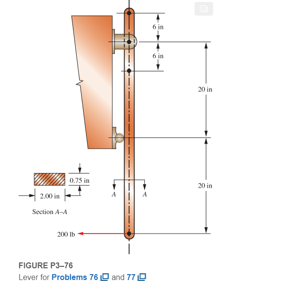
Expert Solution & Answer
Want to see the full answer?
Check out a sample textbook solution
Students have asked these similar questions
Figure P4–49 shows the end of the vertical shaft for a rotary lawn mower. Compute the maximum torsional shear stress in the shaft if it is transmitting 7.5 hp to the blade when rotating 2200 rpm. Specify a suitable steel for the shaft.
This is a subject of Strength of MAterials, COmpute exactly without shortcut.Show FREE BODY DIAGRAM and COMPLETE SOLUTION thank you
Solve with numerical steps
Chapter 3 Solutions
Machine Elements in Mechanical Design (6th Edition) (What's New in Trades & Technology)
Ch. 3 - A tensile member in a machine structure is...Ch. 3 - Compute the stress in a round bar having a...Ch. 3 - Compute the stress in a rectangular bar having...Ch. 3 - A link in a packaging machine mechanism has a...Ch. 3 - Two circular rods support the 3800 lb weight of a...Ch. 3 - A tensile load of 5.00 kN is applied to a square...Ch. 3 - An aluminum rod is made in the form of a hollow...Ch. 3 - Compute the stress in the middle portion of rod AC...Ch. 3 - Compute the forces in the two angled rods in...Ch. 3 - If the rods from Problem 9 are circular, determine...
Ch. 3 - Repeat Problems 9 and 10 if the angle is 15 .Ch. 3 - Figure P312 shows a small truss spanning between...Ch. 3 - The truss shown in Figure P313 spans a total space...Ch. 3 - Figure P314 shows a short leg for a machine that...Ch. 3 - Consider the short compression member shown in...Ch. 3 - Refer Figure P38 . Each of the pins at A, B, and C...Ch. 3 - Compute the shear stress in the pins connecting...Ch. 3 - Prob. 18PCh. 3 - Prob. 19PCh. 3 - Prob. 20PCh. 3 - Prob. 21PCh. 3 - Compute the torsional shear stress in a circular...Ch. 3 - If the shaft of Problem 22 is 850 mm long and is...Ch. 3 - Compute the torsional shear stress due to a torque...Ch. 3 - Compute the torsional shear stress in a solid...Ch. 3 - Compute the torsional shear stress in a hollow...Ch. 3 - Compute the angle of twist for the hollow shaft of...Ch. 3 - A square steel bar, 25 mm on a side and 650 mm...Ch. 3 - A 3.00 in-diameter steel bar has a flat milled on...Ch. 3 - A commercial steel supplier lists rectangular...Ch. 3 - A beam is simply supported and carries the load...Ch. 3 - For each beam of Problem 31, compute its weight if...Ch. 3 - For each beam of Problem 31, compute the maximum...Ch. 3 - For the beam loading of Figure P334, draw the...Ch. 3 - For the beam loading of Figure P334, design the...Ch. 3 - Figure P336 shows a beam made from 4 in schedule...Ch. 3 - Select an aluminum I-beam shape to carry the load...Ch. 3 - Figure P338 represents a wood joist for a...Ch. 3 - For Problems 39 through 50, draw the free-body...Ch. 3 - Prob. 40PCh. 3 - For Problems 39 through 50, draw the free-body...Ch. 3 - Prob. 42PCh. 3 - Prob. 43PCh. 3 - Prob. 44PCh. 3 - For Problems 39 through 50, draw the free-body...Ch. 3 - For Problems 39 through 50, draw the free-body...Ch. 3 - For Problems 39 through 50, draw the free-body...Ch. 3 - For Problems 4850, draw the free-body diagram of...Ch. 3 - For Problems 4850, draw the free-body diagram of...Ch. 3 - Prob. 50PCh. 3 - Compute the maximum tensile stress in the bracket...Ch. 3 - Compute the maximum tensile and compressive...Ch. 3 - For the lever shown in Figure P353 (a), compute...Ch. 3 - Compute the maximum tensile stress at sections A...Ch. 3 - Prob. 55PCh. 3 - Refer to Figure P38. Compute the maximum tensile...Ch. 3 - Prob. 57PCh. 3 - Refer to P342. Compute the maximum stress in the...Ch. 3 - Refer to P343. Compute the maximum stress in the...Ch. 3 - Prob. 60PCh. 3 - Figure P361 shows a valve stem from an engine...Ch. 3 - The conveyor fixture shown in Figure P362 carries...Ch. 3 - For the flat plate in tension in Figure P363,...Ch. 3 - For Problems 64 through 68, compute the maximum...Ch. 3 - For Problems 64 through 68, compute the maximum...Ch. 3 - For Problems 64 through 68, compute the maximum...Ch. 3 - For Problems 64 through 68, compute the maximum...Ch. 3 - Prob. 68PCh. 3 - Figure P369 shows a horizontal beam supported by a...Ch. 3 - Prob. 70PCh. 3 - Prob. 71PCh. 3 - The beam shown in Figure P372 is a stepped, flat...Ch. 3 - Figure P373 shows a stepped, flat bar having a...Ch. 3 - Figure P374 shows a bracket carrying opposing...Ch. 3 - Prob. 75PCh. 3 - Figure P376 shows a lever made from a rectangular...Ch. 3 - For the lever in P376, determine the maximum...Ch. 3 - Figure P378 shows a shaft that is loaded only in...Ch. 3 - Prob. 79PCh. 3 - Prob. 80PCh. 3 - A hanger is made from ASTM A36 structural steel...Ch. 3 - A coping saw frame shown in Figure P382 is made...Ch. 3 - Prob. 83PCh. 3 - Figure P384 shows a hand garden tool used to break...Ch. 3 - Figure P385 shows a basketball backboard and goal...Ch. 3 - Prob. 86P
Knowledge Booster


Learn more about
Need a deep-dive on the concept behind this application? Look no further. Learn more about this topic, mechanical-engineering and related others by exploring similar questions and additional content below.Similar questions
- Compute the tensile stress for the rod shown in Fig. 1 at section A-A, the shearing stress across section B, the compressive stress between the pin and the rod, and the compressive stress between the pin and the yoke. Given n = 1 (3 / 4) in., a = (15 / 32) in., e = (27 / 32) in., b = (15 / 16) in., d = (19 / 32) in., f = 1".arrow_forwardThe force P3 to make it to equilibrium in kN is The Stress in section 1 in N/mm2 is The Compressive Stress in section 2 in N/mm2 is The stress in section 3 in N/mm2 is The total change in length in x10-3 mm isarrow_forwardDirect a key d the Hub Shear plane Hub Key F2 y, or anical F1 T=Torque Shaft T=F(D/2) F = Force of shaft on key F= Force of hub on key Side view -D Shaft diameter End view Shear Shaft plane Hub F1 Key F2 Shear area = A, = bxL %3D Enlarged view of key Pictorial sketch of key, shaft, and hub Ноуarrow_forward
- Calculate the internal force (positive if tensile, negative if compressive) in rod (3). Use a FBD cutting through the rod in the section that includes the free end A.Answer: F3 = Enter your answer in accordance to the question statement kips.arrow_forwardFigure P1-71 shows a riveted butt joint with cover plates connecting two steel plates. Compute the 1-71. shear stress in the rivets due to a force of 10.2 kN applied to the plates.arrow_forward3-67: A short post is made by welding steel plates into a square. as shown in Figure P3-67, and then filling the area inside with concrete. Compute the stress in the steel and in the concrete if b = 1500 mm and t = 10mm, and the post carries an axial load of 900 kN. See Section 2-10 for concrete properties. Use f'c = 6000 psi.arrow_forward
- For the stresses given with the cube below: 1. Compute the center, radius (R), principal normal stresses (0₁ and 03), max shear stress (Tmax) and draw the Mohr's Circle. 2. Compute the normal and shear stresses when the cube is rotated 20° clockwise from the horizontal plane and draw them on the cube. 3. The yield point stress (σyp) is 6 kPa. Determine if the material will fail under stresses shown using Tresca's Hexagon. вкра акра 6 экра 8 кра экра 4краarrow_forward2.A lever secured to a 2 inches round shaft by a steel tapered pin (d = 3/8”) has a pull of 50 lbs at a 30 inch radius from shaft center. Find the unit working stress of the pin.arrow_forward3-103: A circular rod with a diameter of 10.0 mm has a groove cut to a diameter of 8.0 mm. A full radius of 1.20 mm is produced at the bottom of the groove. Compute the maximum stress in the rod when an axial tensile force of 5500 N is applied.arrow_forward
- For the following problem please show intermediate steps including free body diagrams, equation used, problem setup etc. so that your approach can be followed. Finally please put the answer in a box with the appropriate unit.arrow_forwardPLEASE ANSWER NUMBER 1 MECH 222: PLEASE GIVE DETAILED SOLUTIONS AND CORRECT ANSWERS. I WILL REPORT TO BARTLEBY THOSE TUTORS WHO WILL GIVE INCORRECT ANSWERS.arrow_forwardpls help ASAParrow_forward
arrow_back_ios
SEE MORE QUESTIONS
arrow_forward_ios
Recommended textbooks for you
 Mechanics of Materials (MindTap Course List)Mechanical EngineeringISBN:9781337093347Author:Barry J. Goodno, James M. GerePublisher:Cengage Learning
Mechanics of Materials (MindTap Course List)
Mechanical Engineering
ISBN:9781337093347
Author:Barry J. Goodno, James M. Gere
Publisher:Cengage Learning
Basic Fabrication Techniques; Author: Weld.com;https://www.youtube.com/watch?v=3OW7iRnC8Ck;License: Standard Youtube License