
Machine Elements in Mechanical Design (6th Edition) (What's New in Trades & Technology)
6th Edition
ISBN: 9780134441184
Author: Robert L. Mott, Edward M. Vavrek, Jyhwen Wang
Publisher: PEARSON
expand_more
expand_more
format_list_bulleted
Concept explainers
Videos
Textbook Question
Chapter 3, Problem 69P
Figure P3−69 shows a horizontal beam supported by a vertical tension link. The cross sections of both the beam and the link are 20 mm square. All connections use 8.00 mm-diameter cylindrical pins in double shear. Compute the tensile stress in member A-B, the stress due to bending in C-D, and the shearing stress in the pins A and C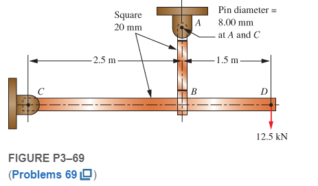
Expert Solution & Answer
Want to see the full answer?
Check out a sample textbook solution
Chapter 3 Solutions
Machine Elements in Mechanical Design (6th Edition) (What's New in Trades & Technology)
Ch. 3 - A tensile member in a machine structure is...Ch. 3 - Compute the stress in a round bar having a...Ch. 3 - Compute the stress in a rectangular bar having...Ch. 3 - A link in a packaging machine mechanism has a...Ch. 3 - Two circular rods support the 3800 lb weight of a...Ch. 3 - A tensile load of 5.00 kN is applied to a square...Ch. 3 - An aluminum rod is made in the form of a hollow...Ch. 3 - Compute the stress in the middle portion of rod AC...Ch. 3 - Compute the forces in the two angled rods in...Ch. 3 - If the rods from Problem 9 are circular, determine...
Ch. 3 - Repeat Problems 9 and 10 if the angle is 15 .Ch. 3 - Figure P312 shows a small truss spanning between...Ch. 3 - The truss shown in Figure P313 spans a total space...Ch. 3 - Figure P314 shows a short leg for a machine that...Ch. 3 - Consider the short compression member shown in...Ch. 3 - Refer Figure P38 . Each of the pins at A, B, and C...Ch. 3 - Compute the shear stress in the pins connecting...Ch. 3 - Prob. 18PCh. 3 - Prob. 19PCh. 3 - Prob. 20PCh. 3 - Prob. 21PCh. 3 - Compute the torsional shear stress in a circular...Ch. 3 - If the shaft of Problem 22 is 850 mm long and is...Ch. 3 - Compute the torsional shear stress due to a torque...Ch. 3 - Compute the torsional shear stress in a solid...Ch. 3 - Compute the torsional shear stress in a hollow...Ch. 3 - Compute the angle of twist for the hollow shaft of...Ch. 3 - A square steel bar, 25 mm on a side and 650 mm...Ch. 3 - A 3.00 in-diameter steel bar has a flat milled on...Ch. 3 - A commercial steel supplier lists rectangular...Ch. 3 - A beam is simply supported and carries the load...Ch. 3 - For each beam of Problem 31, compute its weight if...Ch. 3 - For each beam of Problem 31, compute the maximum...Ch. 3 - For the beam loading of Figure P334, draw the...Ch. 3 - For the beam loading of Figure P334, design the...Ch. 3 - Figure P336 shows a beam made from 4 in schedule...Ch. 3 - Select an aluminum I-beam shape to carry the load...Ch. 3 - Figure P338 represents a wood joist for a...Ch. 3 - For Problems 39 through 50, draw the free-body...Ch. 3 - Prob. 40PCh. 3 - For Problems 39 through 50, draw the free-body...Ch. 3 - Prob. 42PCh. 3 - Prob. 43PCh. 3 - Prob. 44PCh. 3 - For Problems 39 through 50, draw the free-body...Ch. 3 - For Problems 39 through 50, draw the free-body...Ch. 3 - For Problems 39 through 50, draw the free-body...Ch. 3 - For Problems 4850, draw the free-body diagram of...Ch. 3 - For Problems 4850, draw the free-body diagram of...Ch. 3 - Prob. 50PCh. 3 - Compute the maximum tensile stress in the bracket...Ch. 3 - Compute the maximum tensile and compressive...Ch. 3 - For the lever shown in Figure P353 (a), compute...Ch. 3 - Compute the maximum tensile stress at sections A...Ch. 3 - Prob. 55PCh. 3 - Refer to Figure P38. Compute the maximum tensile...Ch. 3 - Prob. 57PCh. 3 - Refer to P342. Compute the maximum stress in the...Ch. 3 - Refer to P343. Compute the maximum stress in the...Ch. 3 - Prob. 60PCh. 3 - Figure P361 shows a valve stem from an engine...Ch. 3 - The conveyor fixture shown in Figure P362 carries...Ch. 3 - For the flat plate in tension in Figure P363,...Ch. 3 - For Problems 64 through 68, compute the maximum...Ch. 3 - For Problems 64 through 68, compute the maximum...Ch. 3 - For Problems 64 through 68, compute the maximum...Ch. 3 - For Problems 64 through 68, compute the maximum...Ch. 3 - Prob. 68PCh. 3 - Figure P369 shows a horizontal beam supported by a...Ch. 3 - Prob. 70PCh. 3 - Prob. 71PCh. 3 - The beam shown in Figure P372 is a stepped, flat...Ch. 3 - Figure P373 shows a stepped, flat bar having a...Ch. 3 - Figure P374 shows a bracket carrying opposing...Ch. 3 - Prob. 75PCh. 3 - Figure P376 shows a lever made from a rectangular...Ch. 3 - For the lever in P376, determine the maximum...Ch. 3 - Figure P378 shows a shaft that is loaded only in...Ch. 3 - Prob. 79PCh. 3 - Prob. 80PCh. 3 - A hanger is made from ASTM A36 structural steel...Ch. 3 - A coping saw frame shown in Figure P382 is made...Ch. 3 - Prob. 83PCh. 3 - Figure P384 shows a hand garden tool used to break...Ch. 3 - Figure P385 shows a basketball backboard and goal...Ch. 3 - Prob. 86P
Knowledge Booster


Learn more about
Need a deep-dive on the concept behind this application? Look no further. Learn more about this topic, mechanical-engineering and related others by exploring similar questions and additional content below.Similar questions
- Repeat Problem 11.3-9. Use two C 150 × 12.2 steel shapes and assume that E = 205 GPa and L = 6 m.arrow_forwardCompare the angle of twist 1 for a thin-walled circular tube (see figure) calculated from the approximate theory for thin-walled bars with the angle of twist 2 calculated from the exact theory of torsion for circular bars, Express the ratio 12terms of the non-dimensional ratio ß = r/t. Calculate the ratio of angles of twist for ß = 5, 10, and 20. What conclusion about the accuracy of the approximate theory do you draw from these results?arrow_forwardAn inflatable structure used by a traveling circus has the shape of a half-circular cylinder with closed ends (see figure). The fabric and plastic structure is inflated by a small blower and has a radius of 40 ft when fully inflated. A longitudinal scam runs the entire length of the "ridge" of the structure. If the longitudinal scam along the ridge tears open when it is subjected to a tensile load of 540 pounds per inch of seam, what is the factor of safety n against tearing when the internal pressure is 0,5 psi and the structure is fully inflated?arrow_forward
- A safety valve on the top of a tank containing steam under pressure p has a discharge hole of diameter d(see figure). The valve is designed to release the steam when the pressure reaches the value Pmax If the natural length of the spring, is L and its stiffness is k, what should be the dimension ft of the valve? (Express your result as a formula for h.)arrow_forwardA large precast concrete panel for a warehouse is raised using two sets of cables at two lift lines, as shown in the figure part a. Cable 1 has a length L1 = 22 Ft, cable 2 has a length L2= 10 ft, and the distance along the panel between lift points Band D is d = 14 ft (see figure part b). The total weight of the panel is W = 85 kips. Assuming the cable lift Forces F at each lift line are about equal, use the simplified model of one half of the panel in figure part b to perform your analysis for the lift position shown. Find the required cross-sectional area AC of the cable if its breaking stress is 91 ksi and a factor of safety of 4 with respect to failure is desired.arrow_forwardRepeat Problem 6.2-1 but now assume that the steel plate is smaller (0.5 in. × 5 in.) and is aligned with the top of the beam as shown in the figure.arrow_forward
- A cable and pulley system at D is used to bring a 230-lcg pole (ACB) to a vertical position, as shown in the Figure part a. The cable has tensile force T and is attached at C. The length L of the pole is 6.0m, the outer diameter is d = 140 mm. and the wall thickness is t = 12 mm. The pole pivots about a pin at A in figure part b. The allowable shear stress in the pin is 60 MPa and the allowable bearing stress is 90 MPa. Find the minimum diameter of the pin at A in order to support the weight of the pole in the position shown in the figure part a.arrow_forwardRepeat Problem 10.4-41 for the loading shown in the figure.arrow_forwardRepeat Problem 8.5-22 but replace the square tube column with a circular tube having a wall thickness r = 5 mm and the same cross-sectional area (3900 mm2) as that of the square tube in figure b in Problem 8.5-22. Also, add force P. = 120 N at B (a) Find the state of plane stress at C. (b) Find maximum normal stresses and show them on a sketch of a properly oriented element. (c) Find maximum shear stresses and show them on a sketch of a properly oriented element.arrow_forward
- A circular tube of aluminum is subjected to torsion by torques T applied at the ends (see figure). The bar is 24 in. long, and the inside and outside diameters are 1.25 in. and 1.75 in., respectively. It is determined by measurement that the angle of twist is 4° when the torque is 6200 lb-in. Calculate the maximum shear stress in the tube, the shear modulus of elasticity G, and the maximum shear strain (in radians). If the maximum shear strain in the tube is limited to 2.5 × 10⁻³ and the inside diameter is increased to 1.375 in., what is the maximum permissible torque?arrow_forwardA lifeboat hangs from two ship's davits. as shown in the figure. A pin of diameter d = 0.80 in. passes through each davit and supports two pulleys. are on each side of the davit. Cables attached to the lifeboat pass over the pulleys and wind around winches that raise and lower the lifeboat. The lower parts of the cables are vertical and the upper parts make an angle a =15° with the horizontal. The allowable tensile force in each cable is 1800 lb, and the allowable shear stress in the pins is 4000 psi. If the lifeboat weighs 1500 lb, what is the maximum weight that can be carried in the lifeboat?arrow_forwardA high-strength steel drill rod used for boring a hole in the earth has a diameter of 0.5 in. (see figure). The allowable shear stress in the steel is 40 ksi and the shear modulus of elasticity is 11,600 ksi. What is the minimum required length of the rod so that one end of the rod can be twisted 30º with respect to the other end without exceeding the allowable stress? If the shear strain in part (a) is limited to 3.2 × 10⁻³ , what is the minimum required length of the drill rod?arrow_forward
arrow_back_ios
SEE MORE QUESTIONS
arrow_forward_ios
Recommended textbooks for you
 Mechanics of Materials (MindTap Course List)Mechanical EngineeringISBN:9781337093347Author:Barry J. Goodno, James M. GerePublisher:Cengage Learning
Mechanics of Materials (MindTap Course List)
Mechanical Engineering
ISBN:9781337093347
Author:Barry J. Goodno, James M. Gere
Publisher:Cengage Learning
EVERYTHING on Axial Loading Normal Stress in 10 MINUTES - Mechanics of Materials; Author: Less Boring Lectures;https://www.youtube.com/watch?v=jQ-fNqZWrNg;License: Standard YouTube License, CC-BY