
Machine Elements in Mechanical Design (6th Edition) (What's New in Trades & Technology)
6th Edition
ISBN: 9780134441184
Author: Robert L. Mott, Edward M. Vavrek, Jyhwen Wang
Publisher: PEARSON
expand_more
expand_more
format_list_bulleted
Concept explainers
Videos
Textbook Question
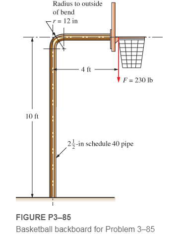
Chapter 3, Problem 85P
Figure P3−85 shows a basketball backboard and goal attached to a steel pipe that is firmly cemented into the ground. The force,
Expert Solution & Answer
Want to see the full answer?
Check out a sample textbook solution
Students have asked these similar questions
Condition #1:
A structural support for a machine is subjected to a static compression load of 20 kN. The support is
manufactured from a circular rod made from SAE 1040 Hot Rolled steel. Specify suitable diameter for
the cross section of the rod based on the basic size. Steel data are available in Table A-10 from the
textbook.
Condition #2:
The same structural support of the basic size determined in Condition 1 is subjected to a tensile load of
15 kN that is repeated several thousand times over the life of the machine. This load is not an addition to
the 20 kN. Specify a suitable steel that is suitable to this application based on the basic size determined in
Condition #1. Loading of Condition #1 does not apply here.
Condition #3:
The same structural support from Condition 2 is heated from room temperature of 25°C. The support is
placed inside a frame on both ends. There is a total clearance of 0.2 mm between the support and its
frame. Initial length of the rod is 200 mm. Specify the…
The force P3 to make it to equilibrium in kN is
The Stress in section 1 in N/mm2 is
The Compressive Stress in section 2 in N/mm2 is
The stress in section 3 in N/mm2 is
The total change in length in x10-3 mm is
The figure below is a schematic drawing of a shaft that supports two V-belt pulleys. The loose belt tension on the pulley at A is 15% of the tension on the tight side. The shaft material has a yield strength of 300 MPa and an ultimate tensile strength of 520 MPa. Calculate the shaft diameter.
Chapter 3 Solutions
Machine Elements in Mechanical Design (6th Edition) (What's New in Trades & Technology)
Ch. 3 - A tensile member in a machine structure is...Ch. 3 - Compute the stress in a round bar having a...Ch. 3 - Compute the stress in a rectangular bar having...Ch. 3 - A link in a packaging machine mechanism has a...Ch. 3 - Two circular rods support the 3800 lb weight of a...Ch. 3 - A tensile load of 5.00 kN is applied to a square...Ch. 3 - An aluminum rod is made in the form of a hollow...Ch. 3 - Compute the stress in the middle portion of rod AC...Ch. 3 - Compute the forces in the two angled rods in...Ch. 3 - If the rods from Problem 9 are circular, determine...
Ch. 3 - Repeat Problems 9 and 10 if the angle is 15 .Ch. 3 - Figure P312 shows a small truss spanning between...Ch. 3 - The truss shown in Figure P313 spans a total space...Ch. 3 - Figure P314 shows a short leg for a machine that...Ch. 3 - Consider the short compression member shown in...Ch. 3 - Refer Figure P38 . Each of the pins at A, B, and C...Ch. 3 - Compute the shear stress in the pins connecting...Ch. 3 - Prob. 18PCh. 3 - Prob. 19PCh. 3 - Prob. 20PCh. 3 - Prob. 21PCh. 3 - Compute the torsional shear stress in a circular...Ch. 3 - If the shaft of Problem 22 is 850 mm long and is...Ch. 3 - Compute the torsional shear stress due to a torque...Ch. 3 - Compute the torsional shear stress in a solid...Ch. 3 - Compute the torsional shear stress in a hollow...Ch. 3 - Compute the angle of twist for the hollow shaft of...Ch. 3 - A square steel bar, 25 mm on a side and 650 mm...Ch. 3 - A 3.00 in-diameter steel bar has a flat milled on...Ch. 3 - A commercial steel supplier lists rectangular...Ch. 3 - A beam is simply supported and carries the load...Ch. 3 - For each beam of Problem 31, compute its weight if...Ch. 3 - For each beam of Problem 31, compute the maximum...Ch. 3 - For the beam loading of Figure P334, draw the...Ch. 3 - For the beam loading of Figure P334, design the...Ch. 3 - Figure P336 shows a beam made from 4 in schedule...Ch. 3 - Select an aluminum I-beam shape to carry the load...Ch. 3 - Figure P338 represents a wood joist for a...Ch. 3 - For Problems 39 through 50, draw the free-body...Ch. 3 - Prob. 40PCh. 3 - For Problems 39 through 50, draw the free-body...Ch. 3 - Prob. 42PCh. 3 - Prob. 43PCh. 3 - Prob. 44PCh. 3 - For Problems 39 through 50, draw the free-body...Ch. 3 - For Problems 39 through 50, draw the free-body...Ch. 3 - For Problems 39 through 50, draw the free-body...Ch. 3 - For Problems 4850, draw the free-body diagram of...Ch. 3 - For Problems 4850, draw the free-body diagram of...Ch. 3 - Prob. 50PCh. 3 - Compute the maximum tensile stress in the bracket...Ch. 3 - Compute the maximum tensile and compressive...Ch. 3 - For the lever shown in Figure P353 (a), compute...Ch. 3 - Compute the maximum tensile stress at sections A...Ch. 3 - Prob. 55PCh. 3 - Refer to Figure P38. Compute the maximum tensile...Ch. 3 - Prob. 57PCh. 3 - Refer to P342. Compute the maximum stress in the...Ch. 3 - Refer to P343. Compute the maximum stress in the...Ch. 3 - Prob. 60PCh. 3 - Figure P361 shows a valve stem from an engine...Ch. 3 - The conveyor fixture shown in Figure P362 carries...Ch. 3 - For the flat plate in tension in Figure P363,...Ch. 3 - For Problems 64 through 68, compute the maximum...Ch. 3 - For Problems 64 through 68, compute the maximum...Ch. 3 - For Problems 64 through 68, compute the maximum...Ch. 3 - For Problems 64 through 68, compute the maximum...Ch. 3 - Prob. 68PCh. 3 - Figure P369 shows a horizontal beam supported by a...Ch. 3 - Prob. 70PCh. 3 - Prob. 71PCh. 3 - The beam shown in Figure P372 is a stepped, flat...Ch. 3 - Figure P373 shows a stepped, flat bar having a...Ch. 3 - Figure P374 shows a bracket carrying opposing...Ch. 3 - Prob. 75PCh. 3 - Figure P376 shows a lever made from a rectangular...Ch. 3 - For the lever in P376, determine the maximum...Ch. 3 - Figure P378 shows a shaft that is loaded only in...Ch. 3 - Prob. 79PCh. 3 - Prob. 80PCh. 3 - A hanger is made from ASTM A36 structural steel...Ch. 3 - A coping saw frame shown in Figure P382 is made...Ch. 3 - Prob. 83PCh. 3 - Figure P384 shows a hand garden tool used to break...Ch. 3 - Figure P385 shows a basketball backboard and goal...Ch. 3 - Prob. 86P
Knowledge Booster


Learn more about
Need a deep-dive on the concept behind this application? Look no further. Learn more about this topic, mechanical-engineering and related others by exploring similar questions and additional content below.Similar questions
- Q3/ Design a helical compression spring made from stainless steel for the following operating conditions: Spring load when the valve is open = 600 N, Spring load when the valve is closed = 250 N, Maximum inside diameter of spring = 25 mm, Length of the spring when the valve is open = 40 mm, Length of the spring when the valve is closed = 50 mm, take into account the Wahl stress factor.arrow_forwardThe pin in the image shown below must transfer an axial tension force of 12.7 kN. Calculate the minimum pin diameter. Use Shear stress=0.4*Yield strength. Assume material is 1020 hot-rolled steel.arrow_forwardA structural support for a machine is subjected to a static compression load of 20 kN. The support is manufactured from a circular rod made from SAE 1040 Hot Rolled steel. Specify suitable diameter for the cross section of the rod based on the basic size. Steel data are available in Table A-10 from the textbook.arrow_forward
- The 200 x 200 x 1,250-mm oak [E-12 GPa] block (2) shown is reinforced by bolting two 5 x 200 x 1,250 mm steel [E - 200 GPa] plates (1) to opposite sides of the block. A concentrated load of 300 kN is applied to a rigid cap. Assume P-300 kN, L-1.25 m. Determine (a) the normal stresses in the steel plates (1) and the oak block (2). (b) the shortening of the block when the load is applied. B (1) Answers: A₁- A₂- i Part 2 Calculate the cross-sectional area of each steel plate, A₁, and the cross-sectional area of the oak block, Az. i Save for Later P CL (2) C Answer: F₂/F₁- CL Save for Later CL (1) mm² mm² Derive a compatibility equation using force-deformation relationships substituted into a geometry-of-deformation relationship. Express the compatibility equation here as the ratio of the force in the oak block, F₂, to the force in each steel plate, F₁. Attempts: 0 of 1 used Submit Answer Attempts: 0 of 1 used Submit Answerarrow_forwardFigure Q1 shows a structure under a concentrated force of P. Pins A, B, E, and F are single-shear with a 21-mm diameter. The connections at D is double shear connection with a 21-mm diameter. All pins are made of Aluminum 2014-T6. Based on yield stress, minimum factor of safety is 1.5 for all parts of below structure. Determine maximum concentrated force P, that can apply on the structure. (The cross sectional area of members EA and FB are 330 mm² and 250 mm² respectively). 350 mm 600 mm 900 mm E Copper Brass C83400 F Copper Bronze C86100 Figure Q1 A B 720 mm P Darrow_forwardCompute the design factor in the middle portion only of the rod AC if the steady vertical force on the boom is 2500 lb. The rod is rectangular, 1.50 in by 3.50 in, and is made from SAE 1144 cold-drawn steel. Include a mohr circle.arrow_forward
- Condition #1: Å structural support for a machine is subjected to a static compression load of 20 kN. The support is manufactured from a circular rod made from SAE 1040 Hot Rolled steel. Specify suitable diameter for the cross section of the rod based on the basic size. Steel data are available in Table A-10 from the textbook.arrow_forward2. The figure shows a spring chair. The chair weight is 100 N. The spring free-length is 500 mm, mean diameter is 200 mm, wire diameter is 10 mm and number of turns is 12. The spring wire material is Music wire A228 with modulus of rigidity of 82700 MPa. Calculate the initial deflection of the spring under the chair weight. If a child seats on the chair, calculate his weight to bush the spring to the shut height. Calculate the stresses in the spring at that condition. BFD'N y = d*G 8FD T = K, 4C +2 K = 4C – 3 D C = --- o00000000odarrow_forwardThe squared and grounded ends of a safety valve with 7.5 coils. The coils measure 105 mm in diameter on the outside and 17 mm wire diameter. It measures 210 mm in free length. 82 Gpa is the modulus of rigidity. Calculate the initial compression length of the wire required to maintain a boiler pressure of 1.35 Mpa on a 30 mm diameter valve seat. (Draw the diagram)arrow_forward
- The figure shows a rigid bar that is supported by a pin at A and two rods, one made of steel and the other of bronze. Neglecting the weight of the bar, compute the force (in N) in the steel rod caused by the 42758-Nload, using the following data: length of steel = 1.27 m, length of bronze = 2.06 m Area of steel = 522 mm, Area of bronze = 239 mm Modulus of elasticity of steel = 216 Gpa, Modulus of elasticity of bronze = 84 Gpa x= 0.69 m, y = 1.08 m, and z = 0.86 m. Round off the final answer to three decimal places. ... Bronze Steel Ey te zarrow_forwardCalculate the reaction forces on the bearing near the pulley and bearing at the far end of the shaft. Include a free body diagram and coordinates. Given the shaft length is 1 meter= Mass=40Kg Static load = 8600N Dynamic (running load) = 8400N Some hints:1. This solution will require you to draw known forces and find unknown reactions in 2perpendicular planes and then add the horizontal and vertical reaction forces asvectors to find the reaction force (hypotenuse).2. Bearings are usually mounted as near as possible to the ends of the shaft withoutfouling the other machine elements. The bearing at the far shaft end can be mountedat the 1 meter point. The bearing at the pulley end should allow clearance to assemblethe pulley.3. Bearing reaction forces are typically simplified as a single point load through thebearing centre.arrow_forwardThe pin in the image shown must transfer an axial tension force of 12.7 kN. Calculate the minimum pin diameter. Use Shear Stress = 0.4*Yield strength. Assume material is 1020 hot-rolled steel.arrow_forward
arrow_back_ios
SEE MORE QUESTIONS
arrow_forward_ios
Recommended textbooks for you
 Mechanics of Materials (MindTap Course List)Mechanical EngineeringISBN:9781337093347Author:Barry J. Goodno, James M. GerePublisher:Cengage Learning
Mechanics of Materials (MindTap Course List)
Mechanical Engineering
ISBN:9781337093347
Author:Barry J. Goodno, James M. Gere
Publisher:Cengage Learning
Fire Safety; Author: Toronto Metropolitan University;https://www.youtube.com/watch?v=7jCyJIJllHE;License: Standard Youtube License