
Machine Elements in Mechanical Design (6th Edition) (What's New in Trades & Technology)
6th Edition
ISBN: 9780134441184
Author: Robert L. Mott, Edward M. Vavrek, Jyhwen Wang
Publisher: PEARSON
expand_more
expand_more
format_list_bulleted
Videos
Textbook Question
Chapter 3, Problem 36P
Figure P3−36 shows a beam made from 4 in schedule 40 steel pipe. Compute the deflection at points A and B for two cases: (a) the simple cantilever and (b) the supported cantilever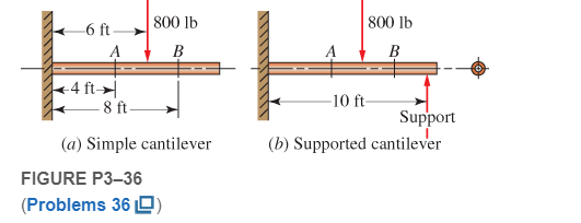
Expert Solution & Answer
Want to see the full answer?
Check out a sample textbook solution
Students have asked these similar questions
Figure P3-36 shows a beam made from 4 in schedule
40 steel pipe. Compute the deflection at points A and
B for two cases: (a) the simple cantilever and (b) the
supported cantilever.
-6 ft.
+4 ft →
800 lb
B
-8 ft-
(a) Simple cantilever
800 lb
B
-10 ft-
Support
(b) Supported cantilever
Using P3-31. A beam is simply supported and carries the load shown in Figure P3–31. Specify an appropriate steel hollow tubing for the loaded beam shown. Also, determine its maximum deflection using the superposition method.
36. Figure P3-36 shows a beam made from 4 in schedule
40 steel pipe. Compute the deflection at points A and
B for two cases: (a) the simple cantilever and (b) the
supported cantilever.
-6 ft-
4 ft
A
800 lb
B
8 ft-
(a) Simple cantilever
FIGURE P3-36 (Problem 36)
800 lb
B
-10 ft-
Support
(b) Supported cantilever
Chapter 3 Solutions
Machine Elements in Mechanical Design (6th Edition) (What's New in Trades & Technology)
Ch. 3 - A tensile member in a machine structure is...Ch. 3 - Compute the stress in a round bar having a...Ch. 3 - Compute the stress in a rectangular bar having...Ch. 3 - A link in a packaging machine mechanism has a...Ch. 3 - Two circular rods support the 3800 lb weight of a...Ch. 3 - A tensile load of 5.00 kN is applied to a square...Ch. 3 - An aluminum rod is made in the form of a hollow...Ch. 3 - Compute the stress in the middle portion of rod AC...Ch. 3 - Compute the forces in the two angled rods in...Ch. 3 - If the rods from Problem 9 are circular, determine...
Ch. 3 - Repeat Problems 9 and 10 if the angle is 15 .Ch. 3 - Figure P312 shows a small truss spanning between...Ch. 3 - The truss shown in Figure P313 spans a total space...Ch. 3 - Figure P314 shows a short leg for a machine that...Ch. 3 - Consider the short compression member shown in...Ch. 3 - Refer Figure P38 . Each of the pins at A, B, and C...Ch. 3 - Compute the shear stress in the pins connecting...Ch. 3 - Prob. 18PCh. 3 - Prob. 19PCh. 3 - Prob. 20PCh. 3 - Prob. 21PCh. 3 - Compute the torsional shear stress in a circular...Ch. 3 - If the shaft of Problem 22 is 850 mm long and is...Ch. 3 - Compute the torsional shear stress due to a torque...Ch. 3 - Compute the torsional shear stress in a solid...Ch. 3 - Compute the torsional shear stress in a hollow...Ch. 3 - Compute the angle of twist for the hollow shaft of...Ch. 3 - A square steel bar, 25 mm on a side and 650 mm...Ch. 3 - A 3.00 in-diameter steel bar has a flat milled on...Ch. 3 - A commercial steel supplier lists rectangular...Ch. 3 - A beam is simply supported and carries the load...Ch. 3 - For each beam of Problem 31, compute its weight if...Ch. 3 - For each beam of Problem 31, compute the maximum...Ch. 3 - For the beam loading of Figure P334, draw the...Ch. 3 - For the beam loading of Figure P334, design the...Ch. 3 - Figure P336 shows a beam made from 4 in schedule...Ch. 3 - Select an aluminum I-beam shape to carry the load...Ch. 3 - Figure P338 represents a wood joist for a...Ch. 3 - For Problems 39 through 50, draw the free-body...Ch. 3 - Prob. 40PCh. 3 - For Problems 39 through 50, draw the free-body...Ch. 3 - Prob. 42PCh. 3 - Prob. 43PCh. 3 - Prob. 44PCh. 3 - For Problems 39 through 50, draw the free-body...Ch. 3 - For Problems 39 through 50, draw the free-body...Ch. 3 - For Problems 39 through 50, draw the free-body...Ch. 3 - For Problems 4850, draw the free-body diagram of...Ch. 3 - For Problems 4850, draw the free-body diagram of...Ch. 3 - Prob. 50PCh. 3 - Compute the maximum tensile stress in the bracket...Ch. 3 - Compute the maximum tensile and compressive...Ch. 3 - For the lever shown in Figure P353 (a), compute...Ch. 3 - Compute the maximum tensile stress at sections A...Ch. 3 - Prob. 55PCh. 3 - Refer to Figure P38. Compute the maximum tensile...Ch. 3 - Prob. 57PCh. 3 - Refer to P342. Compute the maximum stress in the...Ch. 3 - Refer to P343. Compute the maximum stress in the...Ch. 3 - Prob. 60PCh. 3 - Figure P361 shows a valve stem from an engine...Ch. 3 - The conveyor fixture shown in Figure P362 carries...Ch. 3 - For the flat plate in tension in Figure P363,...Ch. 3 - For Problems 64 through 68, compute the maximum...Ch. 3 - For Problems 64 through 68, compute the maximum...Ch. 3 - For Problems 64 through 68, compute the maximum...Ch. 3 - For Problems 64 through 68, compute the maximum...Ch. 3 - Prob. 68PCh. 3 - Figure P369 shows a horizontal beam supported by a...Ch. 3 - Prob. 70PCh. 3 - Prob. 71PCh. 3 - The beam shown in Figure P372 is a stepped, flat...Ch. 3 - Figure P373 shows a stepped, flat bar having a...Ch. 3 - Figure P374 shows a bracket carrying opposing...Ch. 3 - Prob. 75PCh. 3 - Figure P376 shows a lever made from a rectangular...Ch. 3 - For the lever in P376, determine the maximum...Ch. 3 - Figure P378 shows a shaft that is loaded only in...Ch. 3 - Prob. 79PCh. 3 - Prob. 80PCh. 3 - A hanger is made from ASTM A36 structural steel...Ch. 3 - A coping saw frame shown in Figure P382 is made...Ch. 3 - Prob. 83PCh. 3 - Figure P384 shows a hand garden tool used to break...Ch. 3 - Figure P385 shows a basketball backboard and goal...Ch. 3 - Prob. 86P
Knowledge Booster


Learn more about
Need a deep-dive on the concept behind this application? Look no further. Learn more about this topic, mechanical-engineering and related others by exploring similar questions and additional content below.Similar questions
- Solve Problem 11.3-3 for a W 10 × 45 steel column having a length L = 28 ft.arrow_forward2. The figure shows a spring chair. The chair weight is 100 N. The spring free-length is 500 mm, mean diameter is 200 mm, wire diameter is 10 mm and number of turns is 12. The spring wire material is Music wire A228 with modulus of rigidity of 82700 MPa. Calculate the initial deflection of the spring under the chair weight. If a child seats on the chair, calculate his weight to bush the spring to the shut height. Calculate the stresses in the spring at that condition. BFD'N y = d*G 8FD T = K, 4C +2 K = 4C – 3 D C = --- o00000000odarrow_forwardContinue with Questions 1-3 above. What is the deflection at point C. (It will be easier use Castigliano’s theorem.) P B- L. L.arrow_forward
- Figure 2 (b) Compute the stiffness matrix D-1 for D in (a) by using Cramer's rule. List the forces needed to produce a deflection of 0.04 inch at point 3, with zero deflections at the other points.arrow_forwardFind the slope deflections using unit load method or any other method in the text book. For the beam shown in figure below: the beam has a flexural rigidity of El. L= 28 mm Finding the vertical deviationarrow_forwardFrom the given beam shown below, compute the following: 20 mm 80 mm 160 mm NA 1.0 m 1.0m H– 20 mm 1. Distance between top of the beam to Neutral Axis or "c top". 2. Moment of Inertia at Neutral Axis or "I" 3. What is the maximum safe value of P if the working stress in shear is 6 MPa? 4. Using the maximum safe value of P what is the Maximum shear? 5. Using the maximum safe value of P what is the Maximum Moment?arrow_forward
- Use the slope deflection method by using the graphical method to calculate deflections and draw bending moment diagrams then draw the shear force, axial force and bending moment diagrams.arrow_forward52. Compute the maximum tensile and compressive stresses in the horizontal beam shown in Figure P3-52. 6 ft -W 8x10 beam -4 ft 8 ft - 1800 lbarrow_forwardClasswork Problem 2 Draw the Shear Force Diagram (SFD) and Bending Moment Diagram (BMD) for a loaded simply supported beam shown below 1KN 5kN 2kN 4KN 1m 1m 2m 1m 1m 14arrow_forward
- Draw the V and M diagrams, find the deflection under the 75 klb load and the displacement of point C, Find also The rotation at point Aarrow_forward1. Question: With a pin on the AB beam A and a short lever BC as shown in the figure is supported. A, B and C pins have a diameter of 18 mm. P and a are given together Take as values given opposite your names in the table. This upload is above, below in your name on the pin (column 5 Calculate the shear stress occurring on only one of the specified pins A, B and C). P(kN)=30 a(0)=60 pin=A 4P 2P 0.5 m 4P 0.5m 1.5 m 1.5 m Barrow_forwardSince the allowable normal stress of AC beam loaded with uniformly distributed load is 100MPa in tensile, 120MPa in compression and 50MPa in shear stress, check whether the beam is safe.arrow_forward
arrow_back_ios
SEE MORE QUESTIONS
arrow_forward_ios
Recommended textbooks for you
 Mechanics of Materials (MindTap Course List)Mechanical EngineeringISBN:9781337093347Author:Barry J. Goodno, James M. GerePublisher:Cengage Learning
Mechanics of Materials (MindTap Course List)
Mechanical Engineering
ISBN:9781337093347
Author:Barry J. Goodno, James M. Gere
Publisher:Cengage Learning
Mechanical SPRING DESIGN Strategy and Restrictions in Under 15 Minutes!; Author: Less Boring Lectures;https://www.youtube.com/watch?v=dsWQrzfQt3s;License: Standard Youtube License