
Machine Elements in Mechanical Design (6th Edition) (What's New in Trades & Technology)
6th Edition
ISBN: 9780134441184
Author: Robert L. Mott, Edward M. Vavrek, Jyhwen Wang
Publisher: PEARSON
expand_more
expand_more
format_list_bulleted
Concept explainers
Videos
Textbook Question
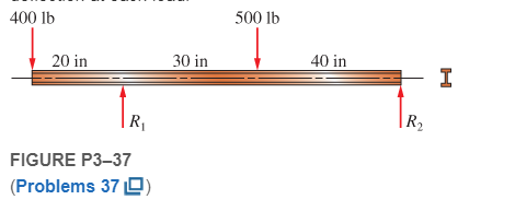
Chapter 3, Problem 37P
Select an aluminum I-beam shape to carry the load shown in Figure P3−37 with a maximum stress of 12 000 psi. Then compute the deflection at each load.
Expert Solution & Answer

Trending nowThis is a popular solution!

Students have asked these similar questions
Using P3-31. A beam is simply supported and carries the load shown in Figure P3–31. Specify an appropriate steel hollow tubing for the loaded beam shown. Also, determine its maximum deflection using the superposition method.
A gear reduction unit uses the countershaft shown in the figure. Gear A receives power from another gear with the transmitted force
FA applied at the 20° pressure angle as shown. The power is transmitted through the shaft and delivered through gear B through a
transmitted force Fg at the pressure angle shown. For the steel countershaft specified in the table, find the deflection and slope of the
shaft at point A. Use superposition with the deflection equations in Table A-9. Assume the bearings constitute simple supports. In the
figure below, FA is 11400 N and the diameter of the shaft (dshaft) is 52 mm.
20⁰
400 mm
Gear A, 600-mm dia.
350 mm
300 mm
Gear B, 300-mm dia.
The deflection at point A is
The slope at point A is 0.0041 rad.
2.2 mm.
25°
✓
dshaft
Since the allowable normal stress of AC beam loaded with uniformly distributed load is 100MPa in tensile, 120MPa in compression and 50MPa in shear stress, check whether the beam is safe.
Chapter 3 Solutions
Machine Elements in Mechanical Design (6th Edition) (What's New in Trades & Technology)
Ch. 3 - A tensile member in a machine structure is...Ch. 3 - Compute the stress in a round bar having a...Ch. 3 - Compute the stress in a rectangular bar having...Ch. 3 - A link in a packaging machine mechanism has a...Ch. 3 - Two circular rods support the 3800 lb weight of a...Ch. 3 - A tensile load of 5.00 kN is applied to a square...Ch. 3 - An aluminum rod is made in the form of a hollow...Ch. 3 - Compute the stress in the middle portion of rod AC...Ch. 3 - Compute the forces in the two angled rods in...Ch. 3 - If the rods from Problem 9 are circular, determine...
Ch. 3 - Repeat Problems 9 and 10 if the angle is 15 .Ch. 3 - Figure P312 shows a small truss spanning between...Ch. 3 - The truss shown in Figure P313 spans a total space...Ch. 3 - Figure P314 shows a short leg for a machine that...Ch. 3 - Consider the short compression member shown in...Ch. 3 - Refer Figure P38 . Each of the pins at A, B, and C...Ch. 3 - Compute the shear stress in the pins connecting...Ch. 3 - Prob. 18PCh. 3 - Prob. 19PCh. 3 - Prob. 20PCh. 3 - Prob. 21PCh. 3 - Compute the torsional shear stress in a circular...Ch. 3 - If the shaft of Problem 22 is 850 mm long and is...Ch. 3 - Compute the torsional shear stress due to a torque...Ch. 3 - Compute the torsional shear stress in a solid...Ch. 3 - Compute the torsional shear stress in a hollow...Ch. 3 - Compute the angle of twist for the hollow shaft of...Ch. 3 - A square steel bar, 25 mm on a side and 650 mm...Ch. 3 - A 3.00 in-diameter steel bar has a flat milled on...Ch. 3 - A commercial steel supplier lists rectangular...Ch. 3 - A beam is simply supported and carries the load...Ch. 3 - For each beam of Problem 31, compute its weight if...Ch. 3 - For each beam of Problem 31, compute the maximum...Ch. 3 - For the beam loading of Figure P334, draw the...Ch. 3 - For the beam loading of Figure P334, design the...Ch. 3 - Figure P336 shows a beam made from 4 in schedule...Ch. 3 - Select an aluminum I-beam shape to carry the load...Ch. 3 - Figure P338 represents a wood joist for a...Ch. 3 - For Problems 39 through 50, draw the free-body...Ch. 3 - Prob. 40PCh. 3 - For Problems 39 through 50, draw the free-body...Ch. 3 - Prob. 42PCh. 3 - Prob. 43PCh. 3 - Prob. 44PCh. 3 - For Problems 39 through 50, draw the free-body...Ch. 3 - For Problems 39 through 50, draw the free-body...Ch. 3 - For Problems 39 through 50, draw the free-body...Ch. 3 - For Problems 4850, draw the free-body diagram of...Ch. 3 - For Problems 4850, draw the free-body diagram of...Ch. 3 - Prob. 50PCh. 3 - Compute the maximum tensile stress in the bracket...Ch. 3 - Compute the maximum tensile and compressive...Ch. 3 - For the lever shown in Figure P353 (a), compute...Ch. 3 - Compute the maximum tensile stress at sections A...Ch. 3 - Prob. 55PCh. 3 - Refer to Figure P38. Compute the maximum tensile...Ch. 3 - Prob. 57PCh. 3 - Refer to P342. Compute the maximum stress in the...Ch. 3 - Refer to P343. Compute the maximum stress in the...Ch. 3 - Prob. 60PCh. 3 - Figure P361 shows a valve stem from an engine...Ch. 3 - The conveyor fixture shown in Figure P362 carries...Ch. 3 - For the flat plate in tension in Figure P363,...Ch. 3 - For Problems 64 through 68, compute the maximum...Ch. 3 - For Problems 64 through 68, compute the maximum...Ch. 3 - For Problems 64 through 68, compute the maximum...Ch. 3 - For Problems 64 through 68, compute the maximum...Ch. 3 - Prob. 68PCh. 3 - Figure P369 shows a horizontal beam supported by a...Ch. 3 - Prob. 70PCh. 3 - Prob. 71PCh. 3 - The beam shown in Figure P372 is a stepped, flat...Ch. 3 - Figure P373 shows a stepped, flat bar having a...Ch. 3 - Figure P374 shows a bracket carrying opposing...Ch. 3 - Prob. 75PCh. 3 - Figure P376 shows a lever made from a rectangular...Ch. 3 - For the lever in P376, determine the maximum...Ch. 3 - Figure P378 shows a shaft that is loaded only in...Ch. 3 - Prob. 79PCh. 3 - Prob. 80PCh. 3 - A hanger is made from ASTM A36 structural steel...Ch. 3 - A coping saw frame shown in Figure P382 is made...Ch. 3 - Prob. 83PCh. 3 - Figure P384 shows a hand garden tool used to break...Ch. 3 - Figure P385 shows a basketball backboard and goal...Ch. 3 - Prob. 86P
Knowledge Booster


Learn more about
Need a deep-dive on the concept behind this application? Look no further. Learn more about this topic, mechanical-engineering and related others by exploring similar questions and additional content below.Similar questions
- -15 A composite beam is constructed froma wood beam (3 in. x 6 in.) and a steel plate (3 in, wide). The wood and the steel are securely fastened to act as a single beam. The beam is subjected to a positive bending moment M. = 75 kip-in. Calculate the required thickness of the steel plate based on the following limit states: Allowable compressive stress in the wood = 2 ksi Allowable tensile stress in the wood = 2 ksi Allowable tensile stress in the steel plate = 16 ksi Assume that Ew= 1,500 ksi and es= 30,000 ksi.arrow_forwardObtain a formula for the ratio c/maxof the deflection at the midpoint to the maximum deflection for a simple beam supporting a concentrated load P (see figure). From the formula, plot a graph of c/max versus the ratio a/L that defines the position of the load (0.5 < a/L < ) What conclusion do you draw from the graph? (Use the formulas of Example 9-3.)arrow_forwardA beam of uniform rectangular section 200 mm wide and 300 mm deep is simply supported at its ends. It carries a uniformly distributed load of 9 KN/m run over the entire span of 5 m. if the value of E for the beam material is 1 X 10⁴ N/mm2 , find the slope at the supports and maximum deflection. Give me complete solution based on the given above. Again I need to ask the same question since you gave me a wrong answer before.arrow_forward
- 700N M-150UNm 2m 3m For the above dlagram, given that F, - 450 N. 0-45 degrees and d-5 m calculate the following (neglect the depth of the beam). Note that there is a pin support at A and a roller support at B. The magnitude of the horizontal component of the reaction force at A, Rar. Please provide the answer in Newtons and report to three significant figures. Please Include the unit ("N") within your answer (eg. If the calculated answer was 55.562 Newtons please Input: 55.6 N). Answer: The magnitude of the vertical component of the reaction force at A, Rar. Please provide the answer in Newtons and report to three significant figures. Please include the unit ("N") within your answer (eg. If the calculated answer was 55.562 Newtons please Input: 55.6 N). Answer: The magnitude of the horizontal component of the reaction force at B. Re. Please provide the answer in Newtons and report to three significant figures. Please Include the unit ("N") within your answer (eg. If the calculated…arrow_forward3. Determine the displacement and slope (i.e. 0) at the load point for the stepped beam shown in the following figure. Also determine the reaction forces and moments. Each element has E = 200 GPa. The area moment of inertia are given as I₁ = 1.25 × 105 mm4, and 2 = 4 x 104 mm. Clearly show the elemental stiffness matrices (k) for each element, assembly of k matrices to get global stiffness matrix (K) and application of boundary conditions. Then solve the reduced K matrix to get displacements and reactions 3000 N 150 mm 75 mm 125 mmarrow_forward52. Compute the maximum tensile and compressive stresses in the horizontal beam shown in Figure P3-52. 6 ft -W 8x10 beam -4 ft 8 ft - 1800 lbarrow_forward
- es A gear reduction unit uses the countershaft shown in the figure. Gear A receives power from another gear with the transmitted force FA applied at the 20° pressure angle as shown. The power is transmitted through the shaft and delivered through gear B through a transmitted force Fg at the pressure angle shown. For the steel countershaft specified in the table, find the deflection and slope of the shaft at point A. Use superposition with the deflection equations in Table A-9. Assume the bearings constitute simple supports. In the figure below, FA is 310 lbf and the diameter of the shaft (dshaft) is 1.29 in. dshaft Gear A 20-in dia. 16 in FA 20⁰ The deflection at point A is The slope at point A is 14 in 100 Gear B 8-in dia. rad. 9 in in. B FB 20°arrow_forwardOn a formatted bond paper, copy and solve the problem. Show your neat and detailed solution. Use three (3) decimal places for your answers and enclosed it in a box. Compute the deflection and slope at a section 8 ft from the wall for the beam shown in the figure using Double Integration Method. Assume that E = 28 x 103 psi and 1= 30.75 1200 lb in4. A 800 lb/ft -8 ft -8 ft Barrow_forwardThe figure shows a cantilever consisting of steel angles size 100 x 100 x 12 mm mounted back to back. Using superposition, find the deflection at B and the maximum stress in the beam. 3 m 2.5 kN - 2 m I kN/m explain every step and define every equation. neat writing.arrow_forward
- The beam is supported by a pin at point A and a roller at point C. A distributed load is applied to the beam. Neglect the weight and thickness of the beam. Hints: 1. will need to use similar triangles to find the height after sectioning at B. 2. Review direction of normal force, shear force and bending moment and which is positive or negative. W2 W1 A di d2 Values for the figure are given in the following table. Note the figure may not be to scale. Variable Value W1 190 N-m W2 440 N-m di 5 m d2 5 m a. Determine the magnitude of the normal force at point B, NB. . b. Determine the magnitude of the shear force at point B, VB- c. Is the shear force VB a positive or negative shear force? d. Determine the magnitude of the bending moment at point B, MB. e. Is the bending moment MB a positive or negative bending moment? Round your final answers to 3 significant digits/figures.arrow_forwardA steel beam of I cross-section is simply supported on a span of 4m. Find the safe uniformly distributed load the beam can carry if the tensile stress is not to exceed 26 N/mm2. Also find the maximum compressive stress.arrow_forwardA simply supported beam carries a concentrated load at the center which fluctuates from a value of W to 4 W. The span of the beam is 497 mm and its cross-section is circular with a diameter of 52 mm. Take ultimate stress of beam material as 687 MPa, Yield stress as 0.55 times ultimate stress and the endurance strength as 0.45 times the value of ultimate stress and take a factor of safety of 1.5. Calculate the maximum value of "W", if the variable stress induced in the beam is 124 N/mm2. Using Goodman relation calculate the value of mean stress in N/mm2.arrow_forward
arrow_back_ios
SEE MORE QUESTIONS
arrow_forward_ios
Recommended textbooks for you
 Mechanics of Materials (MindTap Course List)Mechanical EngineeringISBN:9781337093347Author:Barry J. Goodno, James M. GerePublisher:Cengage Learning
Mechanics of Materials (MindTap Course List)
Mechanical Engineering
ISBN:9781337093347
Author:Barry J. Goodno, James M. Gere
Publisher:Cengage Learning
Solids: Lesson 53 - Slope and Deflection of Beams Intro; Author: Jeff Hanson;https://www.youtube.com/watch?v=I7lTq68JRmY;License: Standard YouTube License, CC-BY