
Machine Elements in Mechanical Design (6th Edition) (What's New in Trades & Technology)
6th Edition
ISBN: 9780134441184
Author: Robert L. Mott, Edward M. Vavrek, Jyhwen Wang
Publisher: PEARSON
expand_more
expand_more
format_list_bulleted
Videos
Textbook Question
Chapter 3, Problem 12P
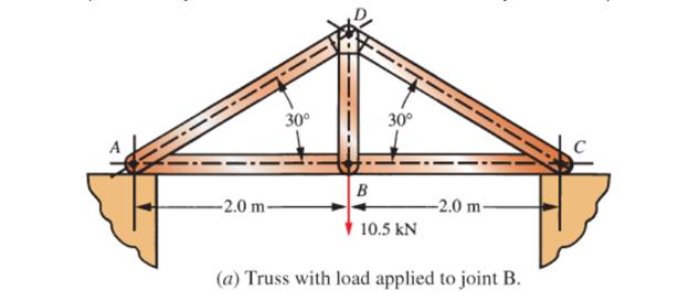
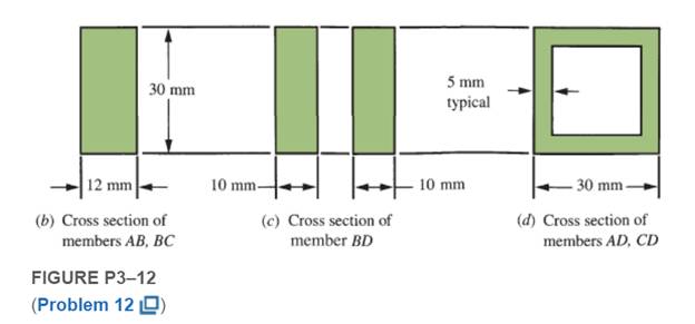
Figure P3−12 shows a small truss spanning between solid supports and suspending a 10.5 kN load. The cross sections for the three main types of truss members are shown. Compute the stresses in all of the members of the truss near their midpoints away from the connections. Consider all joints to be pinned.
Expert Solution & Answer
Want to see the full answer?
Check out a sample textbook solution
Students have asked these similar questions
compute the forces in all members and the stresses in the midsection, away from any joint. Refer to the
Appendix for the cross-sectional area of the members indicated in the figures. Consider all joints to be pinned
30
2.0 m
2.0 m
10.5 kN
(a)
5 mm
30 mm
typical
12 mm
10 mm
10 mm
30 mm
(c)
(d)
(b)
PROBLEM 1: Compute for the force in each member of the truss shown in
FIGURE 1. Indicate in your solutions if the force is in tension or in compression.
FIGURE 1
Height of truss= 0.75
Length of horizontal members= 1.00
60 kN
B
F
25 kN
How many members does the truss have?
How many support reactions does the truss have?
How many joints does the truss have?
Considering the number of supports, joints, and members this truss has,
this truss is considered
What are the force in member:
АВ, ВС, CD, AE, ВЕ, СЕ, ЕF, CF, DF
A small seat angle is used to support a beam with a reaction of 6,000 lbs. Two 1/2 inchdiameter bolts are used to resist the load. Compute the stress in each bolt.
I'm having a hard time with this problem can you help?
Chapter 3 Solutions
Machine Elements in Mechanical Design (6th Edition) (What's New in Trades & Technology)
Ch. 3 - A tensile member in a machine structure is...Ch. 3 - Compute the stress in a round bar having a...Ch. 3 - Compute the stress in a rectangular bar having...Ch. 3 - A link in a packaging machine mechanism has a...Ch. 3 - Two circular rods support the 3800 lb weight of a...Ch. 3 - A tensile load of 5.00 kN is applied to a square...Ch. 3 - An aluminum rod is made in the form of a hollow...Ch. 3 - Compute the stress in the middle portion of rod AC...Ch. 3 - Compute the forces in the two angled rods in...Ch. 3 - If the rods from Problem 9 are circular, determine...
Ch. 3 - Repeat Problems 9 and 10 if the angle is 15 .Ch. 3 - Figure P312 shows a small truss spanning between...Ch. 3 - The truss shown in Figure P313 spans a total space...Ch. 3 - Figure P314 shows a short leg for a machine that...Ch. 3 - Consider the short compression member shown in...Ch. 3 - Refer Figure P38 . Each of the pins at A, B, and C...Ch. 3 - Compute the shear stress in the pins connecting...Ch. 3 - Prob. 18PCh. 3 - Prob. 19PCh. 3 - Prob. 20PCh. 3 - Prob. 21PCh. 3 - Compute the torsional shear stress in a circular...Ch. 3 - If the shaft of Problem 22 is 850 mm long and is...Ch. 3 - Compute the torsional shear stress due to a torque...Ch. 3 - Compute the torsional shear stress in a solid...Ch. 3 - Compute the torsional shear stress in a hollow...Ch. 3 - Compute the angle of twist for the hollow shaft of...Ch. 3 - A square steel bar, 25 mm on a side and 650 mm...Ch. 3 - A 3.00 in-diameter steel bar has a flat milled on...Ch. 3 - A commercial steel supplier lists rectangular...Ch. 3 - A beam is simply supported and carries the load...Ch. 3 - For each beam of Problem 31, compute its weight if...Ch. 3 - For each beam of Problem 31, compute the maximum...Ch. 3 - For the beam loading of Figure P334, draw the...Ch. 3 - For the beam loading of Figure P334, design the...Ch. 3 - Figure P336 shows a beam made from 4 in schedule...Ch. 3 - Select an aluminum I-beam shape to carry the load...Ch. 3 - Figure P338 represents a wood joist for a...Ch. 3 - For Problems 39 through 50, draw the free-body...Ch. 3 - Prob. 40PCh. 3 - For Problems 39 through 50, draw the free-body...Ch. 3 - Prob. 42PCh. 3 - Prob. 43PCh. 3 - Prob. 44PCh. 3 - For Problems 39 through 50, draw the free-body...Ch. 3 - For Problems 39 through 50, draw the free-body...Ch. 3 - For Problems 39 through 50, draw the free-body...Ch. 3 - For Problems 4850, draw the free-body diagram of...Ch. 3 - For Problems 4850, draw the free-body diagram of...Ch. 3 - Prob. 50PCh. 3 - Compute the maximum tensile stress in the bracket...Ch. 3 - Compute the maximum tensile and compressive...Ch. 3 - For the lever shown in Figure P353 (a), compute...Ch. 3 - Compute the maximum tensile stress at sections A...Ch. 3 - Prob. 55PCh. 3 - Refer to Figure P38. Compute the maximum tensile...Ch. 3 - Prob. 57PCh. 3 - Refer to P342. Compute the maximum stress in the...Ch. 3 - Refer to P343. Compute the maximum stress in the...Ch. 3 - Prob. 60PCh. 3 - Figure P361 shows a valve stem from an engine...Ch. 3 - The conveyor fixture shown in Figure P362 carries...Ch. 3 - For the flat plate in tension in Figure P363,...Ch. 3 - For Problems 64 through 68, compute the maximum...Ch. 3 - For Problems 64 through 68, compute the maximum...Ch. 3 - For Problems 64 through 68, compute the maximum...Ch. 3 - For Problems 64 through 68, compute the maximum...Ch. 3 - Prob. 68PCh. 3 - Figure P369 shows a horizontal beam supported by a...Ch. 3 - Prob. 70PCh. 3 - Prob. 71PCh. 3 - The beam shown in Figure P372 is a stepped, flat...Ch. 3 - Figure P373 shows a stepped, flat bar having a...Ch. 3 - Figure P374 shows a bracket carrying opposing...Ch. 3 - Prob. 75PCh. 3 - Figure P376 shows a lever made from a rectangular...Ch. 3 - For the lever in P376, determine the maximum...Ch. 3 - Figure P378 shows a shaft that is loaded only in...Ch. 3 - Prob. 79PCh. 3 - Prob. 80PCh. 3 - A hanger is made from ASTM A36 structural steel...Ch. 3 - A coping saw frame shown in Figure P382 is made...Ch. 3 - Prob. 83PCh. 3 - Figure P384 shows a hand garden tool used to break...Ch. 3 - Figure P385 shows a basketball backboard and goal...Ch. 3 - Prob. 86P
Knowledge Booster


Learn more about
Need a deep-dive on the concept behind this application? Look no further. Learn more about this topic, mechanical-engineering and related others by exploring similar questions and additional content below.Similar questions
- 3) Calculate the internal forces in members DF, CE, and BD of the given truss shown in the figure below. Use the Method of Sections. G0ON GOON GOON GOON G0ON 1,5m 600 N B. 600 N A 6 at 1-20m = 7.20marrow_forwardAssignment-1: Considering the structure shown in the following figure: Calculate the internal forces on each member of the truss using the method of joints and state if the members are in tension or compression. 24 kN 6m 4 m F 8 m 4 m 12 kN 18 kNarrow_forwardThe illustrated truss is subject to certain loads. Calculate the forces acting in the components identified as 3-4, 3-10, and 9-10. Attach your solution (Give, Required, Solution with FBD) 0.8 kip 1.6 kips 2 8 ft 8 1.6 kips 3. 1.6 kips 8 ft 4 8 ft 10 1.6 kips 8 ft 5 1/1 1.6 kips 8 ft 6- 12 0.8 kip 6 ft 8 ft 4.5 ftarrow_forward
- The structure shown below is hinged to fixed supports at A and C. The bars are each 4 in. by 4 in. in section. Compute the maximum tensile stress developed in bar CB assuming the pin connections at A, B, and C are frictionless. 800 lb 5 ft 5 ft C 500 lb 8 ft 6 ft 2 ft -arrow_forwardPROBLEM 1: Compute for the force in each member of the truss shown in FIGURE 1. Indicate in your solutions if the force is in tension or in compression. FIGURE 1 60 kN B E F 25 kN How many members does the truss have? How many support reactions does the truss have? How many joints does the truss have? Considering the number of supports, joints, and members this truss has, this truss is considered What are the force in member: AB, BC, CD, AE, BE, CE, EF, CF, DFarrow_forwardAnswer Problem 6-22 from P. 271 of your textbook and the additional questions below, assuming the stress in cable AB is within the proportional limit. Include a carefully labelled free-body diagram for the pipe strut as part of your solution. Show all work.arrow_forward
- 2. For the truss shown, if all members are made of 1/4" diameter pipe section. Compute the axial stress of members BC and EF in ksi. P load is in kips. (Refer load P to the other attachment) 0.75 P 60 30 E lo' lo' 0.6P 0.3Parrow_forwardFind the normal efforts for truss bars illustrated (draw and compression). Consider loads in kN and dimensions in m. D=4 F=1 Note: Make calculations with extreme precisionarrow_forwardFor the tension member shown, compute the tensile design strength.arrow_forward
- 3. Calculate the bearing stress and shear stress between the pin and each bracket of a clevis joint. Assume pin diameter of 10 mm, 40 mm wide gap link, 12 mm thick bracket, and 3550N tensile load. Draw a free body diagram (geometry & forces) Identify stress plane Calculate stress and write it (with appropriate units) in the outlined boxarrow_forwardCalculate the forces in all members of the truss shown in the following figure and mark the force values in every member. (All horizontal and vertical members are 1m long). 10 kN n o 10 KNarrow_forwardPlease attempt if you know the answer and don't copy from online I will report. Abraced cantilever is loaded as shown in figure. All the members have the same cross sectional area. Find the axial force in the members BC.arrow_forward
arrow_back_ios
SEE MORE QUESTIONS
arrow_forward_ios
Recommended textbooks for you
 Elements Of ElectromagneticsMechanical EngineeringISBN:9780190698614Author:Sadiku, Matthew N. O.Publisher:Oxford University Press
 Mechanics of Materials (10th Edition)Mechanical EngineeringISBN:9780134319650Author:Russell C. HibbelerPublisher:PEARSON
 Thermodynamics: An Engineering ApproachMechanical EngineeringISBN:9781259822674Author:Yunus A. Cengel Dr., Michael A. BolesPublisher:McGraw-Hill Education
 Control Systems EngineeringMechanical EngineeringISBN:9781118170519Author:Norman S. NisePublisher:WILEY
 Mechanics of Materials (MindTap Course List)Mechanical EngineeringISBN:9781337093347Author:Barry J. Goodno, James M. GerePublisher:Cengage Learning
 Engineering Mechanics: StaticsMechanical EngineeringISBN:9781118807330Author:James L. Meriam, L. G. Kraige, J. N. BoltonPublisher:WILEY
Elements Of Electromagnetics
Mechanical Engineering
ISBN:9780190698614
Author:Sadiku, Matthew N. O.
Publisher:Oxford University Press
Mechanics of Materials (10th Edition)
Mechanical Engineering
ISBN:9780134319650
Author:Russell C. Hibbeler
Publisher:PEARSON
Thermodynamics: An Engineering Approach
Mechanical Engineering
ISBN:9781259822674
Author:Yunus A. Cengel Dr., Michael A. Boles
Publisher:McGraw-Hill Education
Control Systems Engineering
Mechanical Engineering
ISBN:9781118170519
Author:Norman S. Nise
Publisher:WILEY
Mechanics of Materials (MindTap Course List)
Mechanical Engineering
ISBN:9781337093347
Author:Barry J. Goodno, James M. Gere
Publisher:Cengage Learning
Engineering Mechanics: Statics
Mechanical Engineering
ISBN:9781118807330
Author:James L. Meriam, L. G. Kraige, J. N. Bolton
Publisher:WILEY
Mechanical SPRING DESIGN Strategy and Restrictions in Under 15 Minutes!; Author: Less Boring Lectures;https://www.youtube.com/watch?v=dsWQrzfQt3s;License: Standard Youtube License