
Foundations of Materials Science and Engineering
6th Edition
ISBN: 9781259696558
Author: SMITH
Publisher: MCG
expand_more
expand_more
format_list_bulleted
Videos
Textbook Question
Chapter 6.13, Problem 48AAP
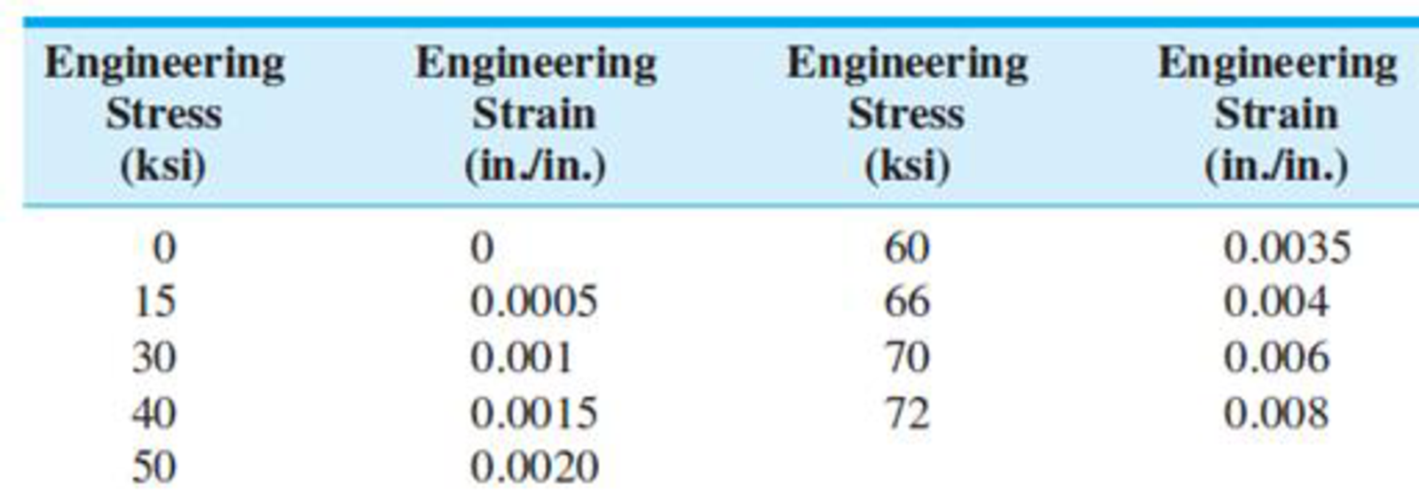
The following engineering stress-strain data were obtained at the beginning of a tensile test for a 0.2% C plain carbon steel. (a) Plot the engineering stress-strain curve for these data. (b) Determine the 0.2% offset yield stress for this steel, (c) Determine the tensile elastic modulus of this steel, (d) Estimate the modulus of resilience. (Note that these data only give the beginning part of the stress-strain curve.)
Expert Solution & Answer
Want to see the full answer?
Check out a sample textbook solution
Students have asked these similar questions
O The following engineering stress-strain data were obtained for a 0.2% C plain-carbon steel.
(i) Plot the engineering stress-strain curve. (ii) Determine the ultimate tensile strength of
the alloy. (iii) Determine the percent elongation at fracture.
Engineering Engineering Engineering Engineering
Stress
Strain
Stress
Strain
(ksi)
(in./in.)
(ksi)
(in./in.)
76
0.08
30
0.001
75
0.10
55
0.002
73
0.12
60
0.005
69
0.14
68
0.010
65
0.16
72
0.020
56
0.18
74
0.040
51
0.19
75
0.060
(Fracture)
70%
+ | 8 0
4.
An application requires ultimate tensile strength and yield strength of
a steel at 110 ksi and 91 ksi, respectively. A data table is attached in the back of
the test. Answer the following 4 questions:
4.1. Can SAE 1040 steel be selected for this application?
4.2. If "no" is the answer in Part I, the following Part II, III, and IV can be
ignored. If "yes" is the answer in Part I, which condition of SAE 1040 should
be selected?
4.3. Why is that steel with the condition in part II selected?
4.4. Is the selected steel brittle or ductile? and Why?
Page 4 of 6
Following is the Tensile stress-strain data for several hypothetical metals to be used.
Answer the following questions referring to table 1.1.
Table 1.1: Material Property Data
Material Tensile Strength
Fracture Strength Strain at Strength
(MPa)
(MPa)
340
265
550
505
112
150
Fracture before yielding
A
B
C
D
0.23
0.15
0.40
a. Which will experience the greatest percent reduction in area? Why?
b. Which is the strongest? Why?
c. Which is the stiffest? Why?
Elastic Modulus
(GPa)
210
310
180
400
Chapter 6 Solutions
Foundations of Materials Science and Engineering
Ch. 6.13 - (a) How are metal alloys made by the casting...Ch. 6.13 - Why are cast metal sheet ingots hot-rolled first...Ch. 6.13 - What type of heat treatment is given to the rolled...Ch. 6.13 - Describe and illustrate the following types of...Ch. 6.13 - Describe the forging process. What is the...Ch. 6.13 - What is the difference between open-die and...Ch. 6.13 - Describe the wire-drawing process. Why is it...Ch. 6.13 - Distinguish between elastic and plastic...Ch. 6.13 - Define (a) engineering stress and strain and (b)...Ch. 6.13 - Define (a) modulus of elasticity, (b) yield...
Ch. 6.13 - (a) Define the hardness of a metal. (b) How is the...Ch. 6.13 - What types of indenters are used in (a) the...Ch. 6.13 - What are slipbands and slip lines? What causes the...Ch. 6.13 - Describe the slip mechanism that enables a metal...Ch. 6.13 - (a) Why does slip in metals usually take place on...Ch. 6.13 - Prob. 16KCPCh. 6.13 - What other types of slip planes are important...Ch. 6.13 - Define the critical resolved shear stress for a...Ch. 6.13 - Describe the deformation twinning process that...Ch. 6.13 - What is the difference between the slip and...Ch. 6.13 - Prob. 21KCPCh. 6.13 - Prob. 22KCPCh. 6.13 - What experimental evidence shows that grain...Ch. 6.13 - (a) Describe the grain shape changes that occur...Ch. 6.13 - How is the ductility of a metal normally affected...Ch. 6.13 - (a) What is solid-solution strengthening? Describe...Ch. 6.13 - What are the three main metallurgical stages that...Ch. 6.13 - Describe the microstructure of a heavily...Ch. 6.13 - Describe what occurs microscopically when a...Ch. 6.13 - When a cold-worked metal is heated into the...Ch. 6.13 - Describe what occurs microscopically when a...Ch. 6.13 - When a cold-worked metal is heated into the...Ch. 6.13 - Prob. 33KCPCh. 6.13 - Prob. 34KCPCh. 6.13 - Prob. 35KCPCh. 6.13 - Prob. 36KCPCh. 6.13 - Prob. 37KCPCh. 6.13 - Why are nanocrystalline materials stronger? Answer...Ch. 6.13 - A 70% Cu30% Zn brass sheet is 0.0955 cm thick and...Ch. 6.13 - A sheet of aluminum alloy is cold-rolled 30% to a...Ch. 6.13 - Calculate the percent cold reduction when an...Ch. 6.13 - Prob. 42AAPCh. 6.13 - What is the relationship between engineering...Ch. 6.13 - A tensile specimen of cartridge brass sheet has a...Ch. 6.13 - A 0.505-in.-diameter rod of an aluminum alloy is...Ch. 6.13 - In Figure 6.23, estimate the toughness of SAE 1340...Ch. 6.13 - The following engineering stress-strain data were...Ch. 6.13 - Prob. 49AAPCh. 6.13 - A 0.505-in.-diameter aluminum alloy test bar is...Ch. 6.13 - A 20-cm-long rod with a diameter of 0.250 cm is...Ch. 6.13 - Prob. 52AAPCh. 6.13 - Prob. 53AAPCh. 6.13 - Prob. 54AAPCh. 6.13 - Prob. 55AAPCh. 6.13 - Prob. 56AAPCh. 6.13 - A specimen of commercially pure titanium has a...Ch. 6.13 - Prob. 58AAPCh. 6.13 - Prob. 59AAPCh. 6.13 - Prob. 60AAPCh. 6.13 - Prob. 61AAPCh. 6.13 - Prob. 62AAPCh. 6.13 - Prob. 63AAPCh. 6.13 - Prob. 64AAPCh. 6.13 - Prob. 65SEPCh. 6.13 - Prob. 66SEPCh. 6.13 - A 20-mm-diameter, 350-mm-long rod made of an...Ch. 6.13 - Prob. 68SEPCh. 6.13 - Prob. 69SEPCh. 6.13 - Consider casting a cube and a sphere on the same...Ch. 6.13 - When manufacturing complex shapes using cold...Ch. 6.13 - Prob. 74SEPCh. 6.13 - Draw a generic engineering stress-strain diagram...Ch. 6.13 - (a) Draw a generic engineering stress-strain...Ch. 6.13 - Prob. 77SEPCh. 6.13 - Prob. 78SEPCh. 6.13 - Prob. 79SEPCh. 6.13 - The material for a rod of cross-sectional area...Ch. 6.13 - What do E, G, v, Ur, and toughness tell you about...Ch. 6.13 - A cylindrical component is loaded in tension until...Ch. 6.13 - Referring to Figures 6.20 and 6.21 (read the...Ch. 6.13 - (a) Show, using the definition of the Poissons...Ch. 6.13 - A one-inch cube of tempered stainless steel (alloy...Ch. 6.13 - Prob. 87SEPCh. 6.13 - Prob. 88SEPCh. 6.13 - Prob. 89SEPCh. 6.13 - Prob. 90SEPCh. 6.13 - Prob. 91SEPCh. 6.13 - Prob. 92SEPCh. 6.13 - Prob. 93SEPCh. 6.13 - Prob. 94SEPCh. 6.13 - Starting with a 2-in.-diameter rod of brass, we...Ch. 6.13 - Prob. 96SEPCh. 6.13 - Prob. 97SEPCh. 6.13 - Prob. 98SEPCh. 6.13 - The cupro-nickel substitutional solid solution...Ch. 6.13 - Prob. 100SEP
Additional Engineering Textbook Solutions
Find more solutions based on key concepts
6–1C A mechanic claims to have developed a car engine that runs on water instead of gasoline. What is your resp...
Thermodynamics: An Engineering Approach
The triple jump is a track-and-field event in which an athlete gets a running start and tries to leap as far as...
Vector Mechanics For Engineers
3.3 It is known that a vertical force of 200 lb is required to remove the nail at C from the board. As the nail...
Vector Mechanics for Engineers: Statics
Define or describe each type of fluid: (a) viscoelastic fluid (b) pseudoplastic fluid (c) dilatant fluid (d) Bi...
Fluid Mechanics: Fundamentals and Applications
Steady state conduction rate to the warm compressor to the net power produces theoretically by thermodynamic ba...
Introduction to Heat Transfer
List several uses of the arbor press.
Machine Tool Practices (10th Edition)
Knowledge Booster


Learn more about
Need a deep-dive on the concept behind this application? Look no further. Learn more about this topic, mechanical-engineering and related others by exploring similar questions and additional content below.Similar questions
- (b) Figure 1 shows, the tensile engineering stress-strain curve for an aluminum alloy. Based on Figure 1, determine: (1) Yield strength (a) (ii) Ultimate Tensile Strength (ors) (ii) Young Modulus (E) | Stress vs Strain 350 300 250 200 150 100 50 0.002 0.004 0.006 0.008 0.01 0.012 0.014 0.016 Strain (mm/mm) Figure 1: Engineering stress-strain curve for aluminum alloy Stress (N/mm2)arrow_forward4. Based on Figure 1 shows, for a carbon steel, the partial tensile engineering stress-strain curve. Determine; (i) Yield strength (o) (ii) Ultimate Tensile Strength (oTs) (ii) Young Modulus (E) 300 2000 10° psi 300 MPa 2000 200 200 1000 1000 100 100 0.000 0.005 0.010 Strain 0.015 0.000 0.020 0.040 0.060 0.080 Strain Figure 1: Engineering stress-strain curve for alloy steel Stress (MPa) Stress Stress (10° psi)arrow_forwardFor a piece of copper alloy, a standard stress test was applied to it, the following data was collected, from which a stress-strain diagram must be generated, where as data it is known that the initial diameter of the element is 0.505in. The analysis must include the following: 1.Modulus of Elasticity and modulus of resilience. 2.Percentage of elongation. 3.Percentage of area reduction. 4.Real and engineering stress at fracture. It is known that after the specimen fractures, its dimensions in terms of length and diameter are 3.014 and 0.374in, respectively.arrow_forward
- Force P and length change AL data are given in table below for the initial portion of a tension test on 7075-T651 Al alloy. The diameter before testing was 9.07 mm., and the gage length Linitial for t length change measurement was 50.8 mm. Calculate corresponding values of engineering stress and strain, and display these values on a stress-strain plot. (use the region for drawing your plot in question sheet) P, kN AL mm 7.22 0.0839 14.34 0.1636 21.06 0.241 0.308 0.380 0.484 0.614 0.924 26.8 31.7 34.1 35.0 36.0 36.5 1.279 36.9 37.2 1.622 1.994arrow_forward5.3) A cold-worked carbon steel was tested in a tensile test and the results are shown in Table 1 below: Table 1. Tensile test results Original diameter 10,00 mm Final diameter 7,60 mm Original gauge length 102,00 mm Final gauge length 114,30 mm Load at upper yield 31,21 kN Maximum force 36,25 kN Load at fracture 28,65 kN Factor of safety 2 For Questions 5.3.1 to 5.3.8, calculate the following tensile test properties based on the information provided in Table 1 above: 5.3.1) Stress at upper yield. ANSWER TO QUESTION 5.3.1 5.3.2) Ultimate tensile stress. ANSWER TO QUESTION 5.3.2arrow_forwardIf material A is observed to have twice the modulus of rigidity but the same Poisson's ratio and yield shear stress than that of material B, then which of the following comparisons is always true? Select one: Material A can resist higher normal stresses than material B can before permanent normal deformations occur. O b For the same load that brings the materials to plastic behavior, material A will experience larger permanent shear deformations than material B. Material A can resist higher shear stresses than material B before permanent shear deformations occur. O d. Material B is has a lower ultimate stress than material A.arrow_forward
- The engineering stress-strain curve below was obtained for a precipitation hardened Aluminum alloy. What is the approximate Yield Strength for this alloy in psi? Engineering Stress Based on Original Area (psi) 50,000 45,000 40,000 35,000 30,000 25,000 20,000 15,000 10,000 5,000 0 O 0.02 0.04 0.06 Aluminum 6061-T6 0.08 0.1 0.12 Engineering Strain (in/in) 0.14 X 0.16 0.18arrow_forwardDraw two schematic graphs using pencil showing a typical stress-strain curve for aluminum. The first graph should show engineering stress vs engineering strain, and the second graph should show true stress vs true strain. Label the showing: (i) elastic modulus (ii) proportional limit (iii) yield stress (iv)yield strain (v) fracture stress (vi) fracture strain on each graph. You may showboth graphs on one plot. Explain the difference between engineering stress and true stress.arrow_forwardThe following observation were made during a tensile test on a mild steel specimen of 40 mm diameter and 200 mm long. Elongation with 40,000 N load (within the limit of proportionality) = 0.0304 mm. yield load = 165,000 N, Maximum load = 245,000 N. Length of the specimen at fracture 252 mm, Determine the yield stress, the modulus of elasticity, the ultimate stress and the percentage elongation.arrow_forward
- : During tensile tests, strain hardening was observed for a metal alloy with a tensile strength of 18,000 psi under regular yielding condition. However, when it was pre-stretched to a 0.5% extension (based on the initial length of the specimen), its strength increased to 20,000 psi. If the pre-extension is increased to 5%, what could be the strength of the material?arrow_forwardThe data shown in the table below were obtained from a tensile test of high-strength steel. The test specimen had a diameter of 13mm and a gage length of 50mm. At fracture, the elongation between the gage marks was 3.0mm and the minimum diameter was 10.7mm. Plot the conventional stress-strain curve for the steel and determine the propotional limit, modulus of elasticity (i.e the slope of the initial part of the stress-strain curve), yield stress at 0.1% offset, ultimate stress, percent elongation in 50mm, and percent reduction area. TENSILE-TEST DATA Load(kN) Elongation(mm) 5 0.005 10 0.015 30 0.048 50 0.084 60 0.099 64.5 0.109 67.0 0.119 68.0 0.137 69.0 0.160 70.0 0.229 72.0 0.259 76.0 0.330 84.0 0.584 92.0 0.853 100.0 1.288 112.0 2.814 113.0 Fracturearrow_forwardThe following data were obtained from the tensile test of Aluminum alloy. The initial diameter of testspecimen was 0.505 inch and gauge length was 2.0 inch. Plot the stress strain diagram and determine(a) Proportional Limit (b) Modulus of Elasticity (c) Yield Stress at 0.2% offset (d) Ultimate Stress and(e) Nominal Rupture Stress.arrow_forward
arrow_back_ios
SEE MORE QUESTIONS
arrow_forward_ios
Recommended textbooks for you
 Elements Of ElectromagneticsMechanical EngineeringISBN:9780190698614Author:Sadiku, Matthew N. O.Publisher:Oxford University Press
 Mechanics of Materials (10th Edition)Mechanical EngineeringISBN:9780134319650Author:Russell C. HibbelerPublisher:PEARSON
 Thermodynamics: An Engineering ApproachMechanical EngineeringISBN:9781259822674Author:Yunus A. Cengel Dr., Michael A. BolesPublisher:McGraw-Hill Education
 Control Systems EngineeringMechanical EngineeringISBN:9781118170519Author:Norman S. NisePublisher:WILEY
 Mechanics of Materials (MindTap Course List)Mechanical EngineeringISBN:9781337093347Author:Barry J. Goodno, James M. GerePublisher:Cengage Learning
 Engineering Mechanics: StaticsMechanical EngineeringISBN:9781118807330Author:James L. Meriam, L. G. Kraige, J. N. BoltonPublisher:WILEY
Elements Of Electromagnetics
Mechanical Engineering
ISBN:9780190698614
Author:Sadiku, Matthew N. O.
Publisher:Oxford University Press
Mechanics of Materials (10th Edition)
Mechanical Engineering
ISBN:9780134319650
Author:Russell C. Hibbeler
Publisher:PEARSON
Thermodynamics: An Engineering Approach
Mechanical Engineering
ISBN:9781259822674
Author:Yunus A. Cengel Dr., Michael A. Boles
Publisher:McGraw-Hill Education
Control Systems Engineering
Mechanical Engineering
ISBN:9781118170519
Author:Norman S. Nise
Publisher:WILEY
Mechanics of Materials (MindTap Course List)
Mechanical Engineering
ISBN:9781337093347
Author:Barry J. Goodno, James M. Gere
Publisher:Cengage Learning
Engineering Mechanics: Statics
Mechanical Engineering
ISBN:9781118807330
Author:James L. Meriam, L. G. Kraige, J. N. Bolton
Publisher:WILEY
Introduction to Ferrous and Non-Ferrous Metals.; Author: Vincent Ryan;https://www.youtube.com/watch?v=zwnblxXyERE;License: Standard Youtube License