
Videos
(a)
The temperature rise in open die forging of cylinder for no friction between the flat dies and the specimen.
(a)
Explanation of Solution
Given:
The initial thickness of the specimen is
The initial radius of the specimen is
The friction coefficient is
Formula used:
The expression for the flow stress is given as,
Here,
The expression for the true strain is given as,
Here,
The expression for the final radius by equating the volume is given as,
The expression for the forging force is given as,
Here,
The expression for the average pressure is given as,
The expression for final height for
The expression for final height for
The expression forfinal height for
The expression for final height for
The expression for final height for
The expression for the temperature rise is given as,
Here
Calculation:
For
The final height can be calculated as,
The final radius can be calculated as,
The true strain can be calculated as,
The flow stress can be calculated as,
Refer to table 2.2 “Typical values of strength coefficient
The average pressure can be calculated as,
The forging force can be calculated as,
For
The final height can be calculated as,
The final radius can be calculated as,
The true strain can be calculated as,
The flow stress can be calculated as,
Refer to table 2.2 “Typical values of strength coefficient
The average pressure can be calculated as,
The forging force can be calculated as,
For
The final height can be calculated as,
The final radius can be calculated as,
The true strain can be calculated as,
The flow stress can be calculated as,
Refer to table 2.2 “Typical values of strength coefficient
The average pressure can be calculated as,
The forging force can be calculated as,
For
The final height can be calculated as,
The final radius can be calculated as,
The true strain can be calculated as,
The flow stress can be calculated as,
Refer to table 2.2 “Typical values of strength coefficient
The average pressure can be calculated as,
The forging force can be calculated as,
For
The final height can be calculated as,
The final radius can be calculated as,
The true strain can be calculated as,
The flow stress can be calculated as,
Refer to table 2.2 “Typical values of strength coefficient
The average pressure can be calculated as,
The forging force can be calculated as,
For
| Reduction (in ) | Forging force (in ) | Area under curve (in ) |
| 2.1635 |
Work done can be calculated by the summation of the area under the curve.
Refer to table of properties of common engineering materials “Typical values of density and heat capacity” for annealed copper is,
Change in temperature can be calculated as,
The figure (1) shows the curve between the forging force and reduction in height.
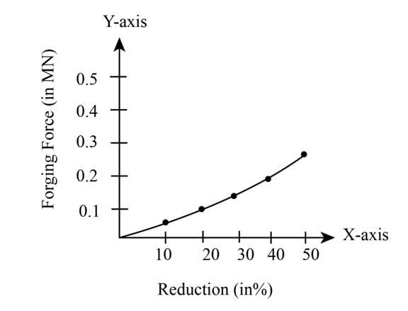
Figure (1)
(b)
The temperature risein open die forging of cylinder for
(b)
Explanation of Solution
Given:
The initial thickness of the specimen is
The initial radius of the specimen is
The friction coefficient is
Formula used:
The expression for the flow stress is given as,
Here,
The expression for the true strain is given as,
Here,
The expression for the final radius by equating the volume is given as,
The expression for the forging force is given as,
Here,
The expression for the average pressure is given as,
The expression for final height for
The expression for final height for
The expression forfinal height for
The expression for final height for
The expression for final height for
The expression for the temperature rise is given as,
Here
Calculation:
For
The final height can be calculated as,
The final radius can be calculated as,
The true strain can be calculated as,
The flow stress can be calculated as,
Refer to table 2.2 “Typical values of strength coefficient
The average pressure can be calculated as,
The forging force can be calculated as,
For
The final height can be calculated as,
The final radius can be calculated as,
The true strain can be calculated as,
The flow stress can be calculated as,
Refer to table 2.2 “Typical values of strength coefficient
The average pressure can be calculated as,
The forging force can be calculated as,
For
The final height can be calculated as,
The final radius can be calculated as,
The true strain can be calculated as,
The flow stress can be calculated as,
Refer to table 2.2 “Typical values of strength coefficient
The average pressure can be calculated as,
The forging force can be calculated as,
For
The final height can be calculated as,
The final radius can be calculated as,
The true strain can be calculated as,
The flow stress can be calculated as,
Refer to table 2.2 “Typical values of strength coefficient
The average pressure can be calculated as,
The forging force can be calculated as,
For
The final height can be calculated as,
The final radius can be calculated as,
The true strain can be calculated as,
The flow stress can be calculated as,
Refer to table 2.2 “Typical values of strength coefficient
The average pressure can be calculated as,
The forging force can be calculated as,
For
| Reduction (in ) | Forging force (in ) | Area under curve (in ) |
Work done can be calculated by the summation of the area under the curve.
Refer to table of properties of common engineering materials “Typical values of density and heat capacity” for annealed copper is,
Change in temperature can be calculated as,
The figure (2) shows the curve between the forging force and reduction in height.
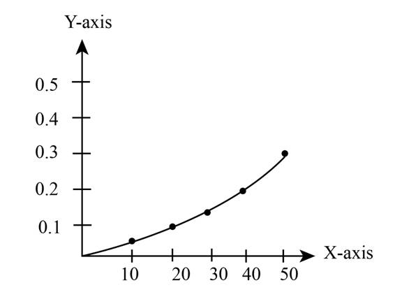
Figure (2)
Want to see more full solutions like this?
Chapter 6 Solutions
EBK MANUFACTURING PROCESSES FOR ENGINEE


- An aluminum specimen subjected to the Brinell hardness test, the indenter and indentation diameters are 14 mm & 4.22 mm respectively. Determine the surface area of indentation, Also, determine the force applied on the aluminum specimen, if Brinell hardness value is 667. Solution: 1. The surface area of Indentation in mm2 is 2. The force applied in N isarrow_forwardA square piece is initially at 10 degrees Celsius everywhere. Each side is 0.05 m long. Then the four sides are instantly heated up to 25 degrees Celsius, 50 degrees Celsius, 30 degrees Celsius, and 0 degrees Celsius. a. Find how long it takes for the temperature profile of this square to become steady if the material is copper. What is the final temperature at the center of the square? b. Find how long it takes for the temperature profile of this square to become steady if the material is air. What is the final temperature at the center of the square? c. Which material takes longer to reach steady state and why?arrow_forwardBlank 1 materials, which behave in a manner similar to Newtonian fluids under time-invariant conditions but, if the shear stress changes suddenly,behave as if plastic.arrow_forward
- A Cu-30% Zn brass plate, originally 1.20 inches thick, is desired to have a yield strength greater than 50,000 psi and a percent elongation of at least 15%. The final geometry of the plate will be obtained by means of cold work. What range of final thicknesses is possible to obtain under the given conditions? The effect of percent cold work on Cu-3096 Zn brass properties is shown below. 100 80 Resistencia a la tensión (ksi) 60 Límite elástico (ksi) 20 Porcentaje de elongación 20 40 60 80 Porcentaje de trabajo en frío Propiedadarrow_forwardA 1.5m diameter spherical balloon containing air at (K + 10) kPa is cooled such that the volume is reducedby 25%. For the process, the pressure is proportional to the square of the sphere’s diameter. What is the workdone by the surrounding? IMPORTANT NOTE: K=821arrow_forwardTwo cylindrical specimens of an alloy are to be strain hardened by reducing their cross- sectional areas. for one specimen. the initial and deformedradii are 17 mm and 12 mm, respectively. The second specimen. with an initial radius of 13 mm, must have the same deformed hardness as the firstspecimen What is the second specimen's radius affer deformation”arrow_forward
- The data below are for a thin steel wire suitable for use as a guitar string. Ultimate tensile stress: 1.8 x 10⁹ Pa Young Modulus: 2.2 x 10¹¹ Pa Cross-sectional area: 2.0 x 10⁻⁷ m2 In a tensile test, a specimen of the wire, of original length 1.5 m, is stretched until it breaks. Assuming the wire obeys Hooke’s law throughout, calculate the extension of the specimen immediately before breaking.arrow_forwardA 2.54-cm. steel bolt is used to clamp two aluminum (2014-T6, HT aged) plates together as shown by Fig. Problem 5. The aluminum plates have a total thickness of 5.08 cm. and an equivalent diameter of 5.08 cm. The bolt is heated to a temperature of 93.33 °C, the inserted in the aluminum plates, which are at 26.7 °C, and tightened so as to have a tensile tightening stress of 207 MPa in the unthreaded shank while steel at 93.33 °C. What is the tensile stress in the bolt after assembly has cooled to 26.7 °C? The deformations are elastic. Fe Aluminum Ports 2D- -D- Grip 2" B Steel- Fearrow_forwardThe strength coefficient and strain-hardening exponent of a certain test metal are 750 MPa and 0.25, respectively. A cylindrical specimen of the metal with starting diameter = 75 mm is stretched. If the average flow stress on the part is 450 MPa determine the final diameter of the specimen.arrow_forward
- The question is: 1-state the objective of the experiment and explain briefly what was done to achieve this objective. 2-explain the effect of the specimen dimeter on the unsteady state heat transfer 3-explain the effect of the specimen material on the unsteady state heat transfer 4-discuss the errors and their sources which might occurred in this experiment and affected its results.arrow_forwardA copper specimen subjected to the Brinell Hardness Test using hardened steel ball indenter of diameter 12 mm and the indentation diameter 3.87 mm is measured using an optical magnifying lens with a ruler. Draw the Brinell Hardness Test setup neatly and determine the force applied on the specimen. Take Brinell Hardness Number for copper as 807. Calculate: 1-Surface Area of Indentation (in mm2) 2-Applied Force (in N)arrow_forwardDetermine the notch sensitivity for the specimen whose maximum stress in notched specimen is 250 MPa and stress in notch free specimen is 100 MPa . The theoretical stress concentration factor is given as 3.arrow_forward
 Principles of Heat Transfer (Activate Learning wi...Mechanical EngineeringISBN:9781305387102Author:Kreith, Frank; Manglik, Raj M.Publisher:Cengage Learning