
Concept explainers
Videos
Consider the CMOS inverter pair in Figure P16.34. Let
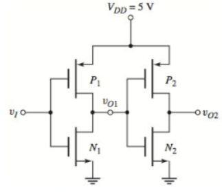
Figure P16.34
Want to see the full answer?
Check out a sample textbook solution
Chapter 16 Solutions
Microelectronics: Circuit Analysis and Design


- Describe the C-V characteristics of a MOS capacitor and explain the physics behind them. 2. Draw the IV curve of a MOSFET for different gate voltages. Explain the characteristics of the curve and dependence on the gate voltage. 3. Explain the structure and operation principle of a CMOS inverter. What are its benefits? 4. Compare SRAM, DRAM and Flash memoriesarrow_forwardDesign the following circuits as shown in the block diagram inverter de chopper ACOVA f = Var Rectif. de CR de=vararrow_forwardA full bridge inverter with RLC load having the following values: R=7.5 Ohms, L=12.5 mH, C-22 uF. The switching frequency is 500 Hz and the DC input voltage is 180V. The average current supply (consider up to the fifth harmonics in calculation) would be equal to: Select one: a. None of these b. 3.84A Ⓒc. 1.64A Ⓒd. 5.74Aarrow_forward
- The duty cycles for 3rd harmonic injection PWM is given by: ki sin(wt)+k2 sin(3wt) da 2 ki sin (wt-)+ką sin(3wt) de ki sin(wt- )+k2 sin(3wt) + 3 do 2 Derive the numeric value of coefficient k1 and k2 to get maximum voltage at the inverterarrow_forward2. Half-bridge inverter is supplied by voltage 400V and is controlled by sinusoidal PWM with modulation index 0.8. What is the value of amplitude of the fundamental component of the AC output voltage? of 1arrow_forwardQ/ for Phase shift (Quasi-Square Wave ) PWM inverter, Vdc=100V, L=25mH, R=10ohm, f=60Hz.draw the spectrum of the output voltage and current and then find the output power, rms current value, and the THD . Take n =1-20. What is the effect of increasing and decreasing L on the output current waveform.arrow_forward
- For the ECL inverter shown in the following sketch, the high voltage level is VH = -1.7V and the average power dissipated when the input is high 50% of the time is P= 5mW. Determine the source's current IEE, the low voltage level VL, the reference voltage level VREF and the value of resistance R3. 2ks2 2k2 VACF -3.3V -5.2V The ECL inverter is the circuit shown. I don't understand what missing. All the information needed is stated.arrow_forwardFor an inverter with VIL = 0.46 V, VIH = 0.77 V, VOL= 0.08 V, and VOH = 1.2 V, find out the maximum value for the noise voltage in presence of which the inverter can work properly. Ans: 0.38 V.arrow_forwardA full bridge inverter with RLC load having the following values: R=7.5 Ohms, L=12.5 mH, C=22 uF. The switching frequency is 500 Hz and the DC input voltage is 180V. The RMS magnitude of the third and fifth harmonics of the load current are respectively equal to: Select one: Oa. 0.3375A, 0.1185A O b. None of these O c. 0.477A, 0.167A d. 0.675A, 0.237Aarrow_forward
- 2r-a 2 -V imini An inverter which produces the output voltage shown the figure above is used to supply the series R (-10[Ohm)) and L(-20[mH) load. Determine the value of a to produce an output with an amplitude of 10 V at the fundamental frequency for the DC input voltage 200 [V] and the output frequency of 60 (Hz).arrow_forwardA CMOS inverter has VDD = 1.8 V, Vtn = 0.5 V, and Kn = µnɛox/2Tox = 125 µA/V?. The ITC for this inverter is plotted below. What is W/L of the nMOS transistor? 2. 3.0е-4 2.5e-4 2.0e-4 1.5e-4 1.0е-4 5.0e-5 0.0e+0 0 0.2 0.4 0.6 0.8 1.0 1.2 1.4 1.6 1.8 Vin (V) IDD (A)arrow_forwardParameter Vro µCoz NMOS 1.0 V 500 μΑ/V2| 200 μΑ/V2 0 v!/2 PMOS -1.0 V 0 v/2 Wmin Lmin 1.0µm 1.0um 0.0 V-1 5 V 1.0μη 1.0µm 0.0 V-1 Vpp Table 1 2. Evaluate the value of noise margins for a static CMOS inverter with parameters given in Table 1. Also calculate the inverter threshold voltage.arrow_forward
 Introductory Circuit Analysis (13th Edition)Electrical EngineeringISBN:9780133923605Author:Robert L. BoylestadPublisher:PEARSON
 Delmar's Standard Textbook Of ElectricityElectrical EngineeringISBN:9781337900348Author:Stephen L. HermanPublisher:Cengage Learning
 Programmable Logic ControllersElectrical EngineeringISBN:9780073373843Author:Frank D. PetruzellaPublisher:McGraw-Hill Education
 Fundamentals of Electric CircuitsElectrical EngineeringISBN:9780078028229Author:Charles K Alexander, Matthew SadikuPublisher:McGraw-Hill Education
 Electric Circuits. (11th Edition)Electrical EngineeringISBN:9780134746968Author:James W. Nilsson, Susan RiedelPublisher:PEARSON
 Engineering ElectromagneticsElectrical EngineeringISBN:9780078028151Author:Hayt, William H. (william Hart), Jr, BUCK, John A.Publisher:Mcgraw-hill Education,