
Videos
In the NMOS circuit in Figure P16.23, the transistor parameters are:
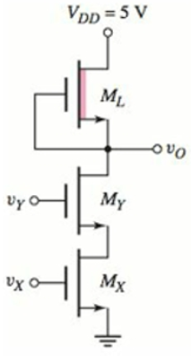
Figure P16.23
Want to see the full answer?
Check out a sample textbook solution
Chapter 16 Solutions
Microelectronics: Circuit Analysis and Design


- HW.3 1-Design a 4 bit Flash ADC. With Vref = 10 V and Vin=4.1V. 2-Find the operation diagram for a 4 bit successive - approximation converter ADCarrow_forward17 Three-phase inverter is supplied by voltage 800V and is controlled by sinusoidal PWM with modulation index 0.8. What is the value of amplitude of the fundamental component of the AC output voltage? 160V 320V 400V 640Varrow_forwardThe parameters of the transistor below are VTN = 0.6 V and Ka = 0.5 mA/V?, find the value of R1, R2, Rp such that IpDQ = 0.5689 mA, VDSQ = 1 V and R1+R=90 k2. Sketch the load line and plot the Q-point. v*= +2.5 V Rp R R2 V---2.5 V wwarrow_forward
- Draw the schematic of a three-input NAND gate. What are the W/L ratios for thetransistors based?arrow_forwardThe parameters of the transistor below are VTN= 0.6 V and K = 0.5 mA/V?, find the value of R1, R2, Rp such that Ipq = 0.5689 mA, VpsQ = 1 V and R1+R=90 k2. Sketch the load line and plot the Q-point. v+ = +2.5 V Rp R1 R2 V-=-2.5 V wwarrow_forwardQ/ for square wave PWM inverter, Vdc=100V, L=25mH, R=10Ω, f=60Hz. draw the spectrum of the output voltage and current and then find the rms current value and the output power. Take n =1-20.arrow_forward
- :- Fill the blanks A. Passive transducers can be classified as Ne B. Noise coupling methods are May mads C. Electronic voltmeters, in general, consist of... D. In the RS485 protocol the logic state is 1 when (exacti state is 0 when................... E. In the USB protocol to send logic 1 the send logic 0 F. Photoelectric devices can be categorized as *********************** and and .........Ve ************ ... and ............... .............. whereas the logic Whereas to andarrow_forwardQ1. A PCM encoder using A-law has a dynamic range of +2 V. Determine the code word when the input signal is (a) -120 mV, (b) 0.5 V, (c) -1.5 V, (d) 1.8 V. determine the input signal value if the code word is (a) 0110 1001, and (b) 1001 1011.arrow_forwardA full bridge inverter with RLC load having the following values: R=7.5 Ohms, L=12.5 mH, C-22 uF. The switching frequency is 500 Hz and the DC input voltage is 180V. The average current supply (consider up to the fifth harmonics in calculation) would be equal to: Select one: a. None of these b. 3.84A Ⓒc. 1.64A Ⓒd. 5.74Aarrow_forward
- for Phase shift PWM inverter, Vdc=100V, L=25mH, R=10ohm, f=60Hz. draw the spectrum of the output voltage and current and then find the rms current value and the output power. Take n =1-20. What is the effect of increasing and decreasing L on the output current waveform.arrow_forward3. PWM Inverter The full bridge inverter is used to produce a 60 Hz voltage across a series R-L load using bipolar PWM. The dc input to the bridge is 100 V, the amplitude modulation ratio ma is 0.8 and the frequency modulation ratio m, is 21. The load has a resistance of R = 10n and a 20mH. Determine the a) the amplitude of the 60-Hz component of the output voltage and load current b) power absorbed by the load resistor c) THD of load series inductance of L current. m,=1 0.9 0.8 0.7 0.6 0.5 0.4 0.3 0.2 0.1 1.00 0.90 0.80 0.70 0.60 0.50 0.40 0.10 0.30 1.20 0.20 1.24 n=1 0.60 0.71 0.82 0.92 1.01 1.08 1.15 1.27 n=m, n=mf±2 0.32 0.27 0.22 0.17 0.13 0.09 0.06 0.03 0.02 0.00arrow_forwardOne half bridge inverter with bidirectional switches and one full bridge inverter with bidirectional switches are connected to similar loads (R=102) and providing both an output power of 1 KW. The rms transistor currents of the half bridge and full bridge inverters are respectively: Select one: O a. 5A, 7.07A O b. 5A, 5A O c. 7.07A, 5A Od. None of thesearrow_forward
 Introductory Circuit Analysis (13th Edition)Electrical EngineeringISBN:9780133923605Author:Robert L. BoylestadPublisher:PEARSON
 Delmar's Standard Textbook Of ElectricityElectrical EngineeringISBN:9781337900348Author:Stephen L. HermanPublisher:Cengage Learning
 Programmable Logic ControllersElectrical EngineeringISBN:9780073373843Author:Frank D. PetruzellaPublisher:McGraw-Hill Education
 Fundamentals of Electric CircuitsElectrical EngineeringISBN:9780078028229Author:Charles K Alexander, Matthew SadikuPublisher:McGraw-Hill Education
 Electric Circuits. (11th Edition)Electrical EngineeringISBN:9780134746968Author:James W. Nilsson, Susan RiedelPublisher:PEARSON
 Engineering ElectromagneticsElectrical EngineeringISBN:9780078028151Author:Hayt, William H. (william Hart), Jr, BUCK, John A.Publisher:Mcgraw-hill Education,