Concept explainers
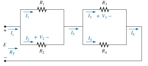
For the network in Fig. 7.70.
a. Does
b. If
c. Does

Fig. 7.70
d. If
e. If
f. If all the resistors of the configuration are 20
g. using the values of part (f), find the power delivered by the battery and the power absorbed by the total resistance RT
Want to see the full answer?
Check out a sample textbook solution
Chapter 7 Solutions
Introductory Circuit Analysis (13th Edition)
Additional Engineering Textbook Solutions
Thermodynamics: An Engineering Approach
Fluid Mechanics: Fundamentals and Applications
Mechanics of Materials (10th Edition)
Java: An Introduction to Problem Solving and Programming (8th Edition)
Vector Mechanics for Engineers: Statics and Dynamics
Automotive Technology: Principles, Diagnosis, And Service (6th Edition) (halderman Automotive Series)
- Question No. 4 hand written withn expanation (a) Design a circuit using D flip-flops that can be used to divide the clock frequency by 16. (b) Draw the input and output waveforms for each stage to the circuit designed in part (a).arrow_forwardhandwritten withn expanation need Question No. 4 ( (a) Design a circuit using D flip-flops that can be used to divide the clock frequency by 16. (b) Draw the input and output waveforms for each stage to the circuit designed in part (a).arrow_forwardDraw and explain the electronic circuit diagram of PID controller, Write its advantages anddisadvantages.arrow_forward
- Written Answer Needed Correct onearrow_forwardINSTRUCTIONS: only electrical engineering experts solve it correct take your 5hrs but solve accurate not ai answers okkkk Only Electrical engineering experts solve it okkMention Written Answer Needed Correct onearrow_forwardI need expert solution not Aiarrow_forward
- Question (a) Design a circuit using D flip-flops that can be used to divide the clock frequency by 16. (b) Draw the input and output waveforms for each stage to the circuit designed in part (a).arrow_forwardDon't use ai to answer I will report you answerarrow_forwardCorrect & written Based Need, No Copy Paste Chatgpt Answerarrow_forward
 Introductory Circuit Analysis (13th Edition)Electrical EngineeringISBN:9780133923605Author:Robert L. BoylestadPublisher:PEARSON
 Delmar's Standard Textbook Of ElectricityElectrical EngineeringISBN:9781337900348Author:Stephen L. HermanPublisher:Cengage Learning
 Programmable Logic ControllersElectrical EngineeringISBN:9780073373843Author:Frank D. PetruzellaPublisher:McGraw-Hill Education
 Fundamentals of Electric CircuitsElectrical EngineeringISBN:9780078028229Author:Charles K Alexander, Matthew SadikuPublisher:McGraw-Hill Education
 Electric Circuits. (11th Edition)Electrical EngineeringISBN:9780134746968Author:James W. Nilsson, Susan RiedelPublisher:PEARSON
 Engineering ElectromagneticsElectrical EngineeringISBN:9780078028151Author:Hayt, William H. (william Hart), Jr, BUCK, John A.Publisher:Mcgraw-hill Education,


