
Introductory Circuit Analysis (13th Edition)
13th Edition
ISBN: 9780133923605
Author: Robert L. Boylestad
Publisher: PEARSON
expand_more
expand_more
format_list_bulleted
Concept explainers
Videos
Textbook Question
Chapter 7, Problem 19P
For the network in Fig. 7.82:
a. Determine the current /1.
b. Calculate the currents /2 and /3.
c. Determine the voltage level Va.
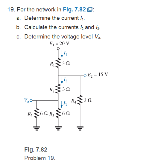
Fig. 7.82
Expert Solution & Answer
Want to see the full answer?
Check out a sample textbook solution
Students have asked these similar questions
3. For the network of Fig. 7.85 , determine:
a. VG.
b. ID and VGS.
c. VD and VS.
d. VDS.
O 20 V
2.2 kn
910 kQ
Dss = 10 mA
V, =-3.5 V
Vasa
110 kQ
1.1 ka
Q: A wood panel containing 16 solar cells. Calculate the total open
circuit voltage and short circuit current coming out of the board and
draw the relationship between current and voltages in the following
cases
a) If you connect each two cells in series and connect the groups in
parallel .
b) If all four cells are connected in parallel and the groups are linked in
succession, noting that each cell has the following characteristics: Vos =
0.75V, Isc = 2 mA
The joules supplied to the battery are..
2. The current through a branch in a linear network is 2A when the input source
voltage is 10 V. If the voltage is reduced to 1 V and the polarity is reversed, the
current through the branch is
Chapter 7 Solutions
Introductory Circuit Analysis (13th Edition)
Ch. 7 - Which elements (individual elements, not...Ch. 7 - Repeat Problem 1 for the networks of Fig. 7.65....Ch. 7 - Determine RT for the networks in Fig. 7.66. Fig....Ch. 7 - Determine RT for the networks in Fig. 7.67. Fig....Ch. 7 - Find the total resistance for the configuration of...Ch. 7 - The total resistance RT for the network of Fig....Ch. 7 - For the network in Fig. 7.70. a. Does...Ch. 7 - For the network in Fig. 7.71: a. Determine RT. b....Ch. 7 - For the network of Fig. 7.72: a. find the currents...Ch. 7 - For the network of Fig. 7.73: Find the voltages V3...
Ch. 7 - For the network of Fig. 7.74 a. Find the voltages...Ch. 7 - For the circuit board in Fig. 7.75: Find the total...Ch. 7 - Find the value of each resistor for the network of...Ch. 7 - Find the resistance RT for the network of Fig....Ch. 7 - For the network in Fig. 7.78: a. Find currents...Ch. 7 - a. Find the magnitude and direction of the...Ch. 7 - Determine the currents I1andI2 for the network in...Ch. 7 - For the network in Fig. 7.81: a. Determine the...Ch. 7 - For the network in Fig. 7.82: a. Determine the...Ch. 7 - Determine the dc levels for the transistor network...Ch. 7 - For the network in Fig. 7.84: Determine the...Ch. 7 - For the network in Fig. 7.852 Determine RT by...Ch. 7 - For the network of Fig. 7.86: a. Find the voltages...Ch. 7 - For the network in Fig. 7.87: a. Determine the...Ch. 7 - For the network in Fig. 7.88 find the resistance...Ch. 7 - If all the resistors of the cube in Fig. 7.89 are...Ch. 7 - For the ladder network in Fig. 7.90: a. Find the...Ch. 7 - For the ladder network in Fig. 7.91: a. Determine...Ch. 7 - Given the voltage divider supply in Fig. 7.92: a....Ch. 7 - Determine the voltage divider supply resistors for...Ch. 7 - A studio lamp requires 40 V at 50 mA to burn...Ch. 7 - For the system in Fig. 7.94 a. At first exposure,...Ch. 7 - For the potentiometer in Fig. 7.95: a. What are...Ch. 7 - Prob. 34PCh. 7 - Given the voltmeter reading V = 27 V in Fig. 7.97...Ch. 7 - Determine the power delivered to the 6 load in...Ch. 7 - For the multiple ladder configuration in Fig....Ch. 7 - An iron-vane movement is rated 1 mA, 100 . a. What...Ch. 7 - Using a 50 A, 1000 movement, design a multirange...Ch. 7 - An iron-vane movement is rated 50 A , 1000 a....Ch. 7 - Using a 1 mA, 1000 movement, design a multirange...Ch. 7 - A digital meter has an internal resistance of 10 M...Ch. 7 - a. Design a series ohmmeter using a 100 A, 1000...Ch. 7 - Prob. 44PCh. 7 - Determine the reading of the ohmmeter for each...Ch. 7 - Using PSpice or Multisim, verify the result of...Ch. 7 - Using PSpice or Multisim, Confirm the solutions of...Ch. 7 - Using PSpice or Multisim, verify the result of...Ch. 7 - Using PSpice or Multisim, find voltage V6 of Fig....Ch. 7 - Using PSpice or Multisim, find voltages Vb and Vc...
Additional Engineering Textbook Solutions
Find more solutions based on key concepts
With respect to the circuit in Fig. 5.90, (a) employ Thévenin’s theorem to determine the equivalent network see...
Loose Leaf for Engineering Circuit Analysis Format: Loose-leaf
The voltage source of the circuit shown in Fig. P1.29 is given by s(t)=25cos(4104t45)(V). Obtain an expression ...
Fundamentals of Applied Electromagnetics (7th Edition)
Electric power systems provide energy in a variety of commercial and industrial settings. Make a list of system...
Principles and Applications of Electrical Engineering
Explain the main function of each of the following major components of a PLC: a. Processor module (CPU) b. I/O ...
Programmable Logic Controllers
A constant voltage of 10V is applied to a 50H inductance, as shown in Figure P3.51 Figure P3 51 The current in ...
Electrical Engineering: Principles & Applications (7th Edition)
What is the color code for a 365- five-band precision resistor with a tolerance of 5 percent?
ELECTRICITY FOR TRADES (LOOSELEAF)
Knowledge Booster


Learn more about
Need a deep-dive on the concept behind this application? Look no further. Learn more about this topic, electrical-engineering and related others by exploring similar questions and additional content below.Similar questions
- i. Analyze the role of ADC and DAC used in a Digital Voltmeter when it is measuring a voltage of 3V with neat sketch of the mentioned. ii. In Al Ahmadi substation, a voltmeter of range (0-300V) and ammeter of range (0-10A) are used to measure a line voltage of 11kV and current of 700A. On a particular day the ammeter shows a reading of 7.5A, then estimate the total line current in the substation. User sample values for winding turns.arrow_forwardCalculate the Equivalent resistance Rabarrow_forwardQ: A wood panel containing 16 solar cells. Calculate the total open circuit voltage and short circuit current coming out of the board and draw the relationship between current and voltages in the following cases 1- If you connect each two cells in series and connect the groups in parallel. 2- If all four cells are connected in parallel and the groups are linked in succession, noting that each cell has the following characteristics: Vos = 0.75V, Isc = 2 mAarrow_forward
- EXAMPLE: Using nodal analysis, determine the potential across the 4-2 resistor and it's current. 50. 50 2 0 . 2 2 2 2 3 Aarrow_forwardThe load across a 50.0-V battery consists of a series combination of two lamps with resistances of 125 $2 Dand 225 N. a. Find the total resistance of the circuit. b. Find the current in the circuit. c. Find the potential difference across the 125-2 Olamp. 21 2, and 15. The load across a 12-V battery consists of a series combination of three resistances are 15 2, 24 N, respectively. a. Draw the circuit diagram. b. What is the total resistance of the load? c. What is the magnitude of the circuit current?arrow_forwardTwo voltmeter of (0-300 V) range are connected in parallel to a A.C. circuit. One voltmeter is moving iron type reads 200 V. If the other is PMMC instrument, its reading will be a)200 V b) slightly less than 200 V c) 0 Varrow_forward
- Problem No. 7 *13. Determine V, and In for the network of Fig. 163. 2 k. Si +10 Vo GaAs 2 k2 2 ka FIG. 163arrow_forwardDetermine v, for the network of fig. 7 for the input indicated. f= 1000 Hz C = 1uF 10 R. 100 k2 -5 V -20 Fig. 7arrow_forward6. What is the maximum instantaneous current that flows in an electrical device rated as 240 V 1500W? A. 3.13 A C. 6.25 A B. 4.42 A D. 8.84 Aarrow_forward
- voltmeter is connected in series on the element when we are taking the reading of the voltage Select the correct response: True Falsearrow_forwardFor the three-way bulb (50 W, 100 W, 150 W), find the resistance of (a)the 100-W filament and (b) the 50-W filament. Assume that the wattage ratings are not limited by significant figures and ignore any heating effects on the resistances.arrow_forward7. (1 P) What is the total resistance of this network if every resistance has the value R.arrow_forward
arrow_back_ios
SEE MORE QUESTIONS
arrow_forward_ios
Recommended textbooks for you
 Introductory Circuit Analysis (13th Edition)Electrical EngineeringISBN:9780133923605Author:Robert L. BoylestadPublisher:PEARSON
 Delmar's Standard Textbook Of ElectricityElectrical EngineeringISBN:9781337900348Author:Stephen L. HermanPublisher:Cengage Learning
 Programmable Logic ControllersElectrical EngineeringISBN:9780073373843Author:Frank D. PetruzellaPublisher:McGraw-Hill Education
 Fundamentals of Electric CircuitsElectrical EngineeringISBN:9780078028229Author:Charles K Alexander, Matthew SadikuPublisher:McGraw-Hill Education
 Electric Circuits. (11th Edition)Electrical EngineeringISBN:9780134746968Author:James W. Nilsson, Susan RiedelPublisher:PEARSON
 Engineering ElectromagneticsElectrical EngineeringISBN:9780078028151Author:Hayt, William H. (william Hart), Jr, BUCK, John A.Publisher:Mcgraw-hill Education,
Introductory Circuit Analysis (13th Edition)
Electrical Engineering
ISBN:9780133923605
Author:Robert L. Boylestad
Publisher:PEARSON
Delmar's Standard Textbook Of Electricity
Electrical Engineering
ISBN:9781337900348
Author:Stephen L. Herman
Publisher:Cengage Learning
Programmable Logic Controllers
Electrical Engineering
ISBN:9780073373843
Author:Frank D. Petruzella
Publisher:McGraw-Hill Education
Fundamentals of Electric Circuits
Electrical Engineering
ISBN:9780078028229
Author:Charles K Alexander, Matthew Sadiku
Publisher:McGraw-Hill Education
Electric Circuits. (11th Edition)
Electrical Engineering
ISBN:9780134746968
Author:James W. Nilsson, Susan Riedel
Publisher:PEARSON
Engineering Electromagnetics
Electrical Engineering
ISBN:9780078028151
Author:Hayt, William H. (william Hart), Jr, BUCK, John A.
Publisher:Mcgraw-hill Education,
Current Divider Rule; Author: Neso Academy;https://www.youtube.com/watch?v=hRU1mKWUehY;License: Standard YouTube License, CC-BY