
Concept explainers
Videos
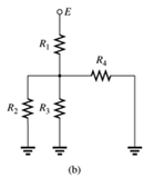
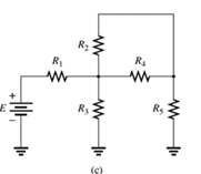
Which elements (individual elements, not combinations of elements) of the networks in Fig. 7.64. are in series? Which are in parallel? As a check on your assumptions, be sure that the elements in series have the same current and that the elements in parallel have the same voltage. Restrict your decisions to single elements not combinations of elements.
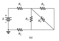
Fig 7.64
(a)
The elements of the network that are in series and in parallel.
Answer to Problem 1P
Explanation of Solution
Given:
A network is given as below.
Concept Used:
Elements in the series have the same current.
Elements in the parallels have the same voltage.
Calculation:
A network is given as below.

Since same current is flowing through
So,
Also, since same voltage is flowing through
So,
Conclusion:
Hence,
(b)
The elements of the network that are in series and in parallel.
Answer to Problem 1P
Explanation of Solution
Given:
A network is given as below.
Concept Used:
Elements in the series have the same current.
Elements in the parallels have the same voltage.
Calculation:
A network is given as below.

Since same current is flowing through
So,
And since same voltage is flowing through
So,
Conclusion:
Hence,
(c)
The elements of the network that are in series and in parallel.
Answer to Problem 1P
Explanation of Solution
Given:
A network is given as below.
Concept Used:
Elements in the series have the same current.
Elements in the parallels have the same voltage.
Calculation:
A network is given as below.

Since same current is flowing through
So,
Since same voltage is across
So,
Conclusion:
Hence,
Want to see more full solutions like this?
Chapter 7 Solutions
Introductory Circuit Analysis (13th Edition)
Additional Engineering Textbook Solutions
Starting Out with Java: From Control Structures through Data Structures (4th Edition) (What's New in Computer Science)
Introduction To Programming Using Visual Basic (11th Edition)
Starting Out with Python (4th Edition)
Degarmo's Materials And Processes In Manufacturing
Computer Science: An Overview (13th Edition) (What's New in Computer Science)
Database Concepts (8th Edition)


- fig. 7.80 for the Gufiguration of © find the currents I2, Is andl Is 5 find the Joltages Vy and us Ri R3 Ru R6 Rs R7 Ri 302 32arrow_forwardFET BIASING 33. For the network of Fig. 7.102, determine: a. Ip, and VGso' b. Vps- c. Vp. C9 9-16 V 2 k2 1 M2 VGs (Th) = -3 V Ip (on) = 4 mA VGs (on) = -7 V Vase FIG. 7.102arrow_forward7U. A d'Arsonval voltmeter is shown below. Find the value of Rv for each of the following full Scale Readings: a) 100 V b)25 V c) 500 mV d) 5 mV Rv 10 mV .2 mA Voltmeterarrow_forward
- is*) The circuit in Figure 7 corresponds to a solar-powered lamp post. The solar panel charges the battery during the day. The battery is used to turn the light ON during the night. is thse th) Use the superposition principle to find the Thevenin voltage at the lamp post terminals (terminals a-b) during the day (when the solar panel is generating power). ii. Calculate the lamp bulb resistance that will ensure the maximum transfer of power from the circuit to the lamp bulb. iii. Find the maximum power that can be delivered to the lamp bulb. 0.3.02 5A Solar panel 10 Ω m 0.3 Ω ww R₁ Lamp post Figure 7 0.10 ww ww 0.1Ω 0.20 12V Batteryarrow_forward3. List the elements in series. List the elements in parallel. Use series and parallel property to reduce the number of unknowns. How many Nodes? (don't count series nodes if you are using Series property). How many KCL can you write? How many independent loops? How many KVL can you write? (if you are using the parallel property then don't write KVL of loops with parallel elements) Introduce the appropriate unknowns for each element (show the direction or terminals of the unknown). Write the necessary KCL and KVL to solve the circuit. Solve the unknowns and find the powers of both sources, specify as absorb or supply. 2 ΚΩ 2000 4 kn V₂ m 13 ΚΩarrow_forwardA current of 8A was measured from a load to which a 220v voltage source is applied.The internal resistance of the voltmeter is Rv = 20Kohm, the internal resistance of the ammeter is according to 0.2 ohms. A) First draw the connecting circuit and find the errors B) then draw the connecting circuit and find the errors C) Evaluate and interpret the errors detected in items a and b.arrow_forward
- Homework of Lec.7.. Tlectrical Circuits I Asst.Lect. Faten Imad Ali Lecture Seven Homework: I) Calculate Thevenin equivalent circuit between the open terminals A and B of the circuit. 2) Using Norton Theorem find the current and voltage for the network extenal to resistor R. R22 kn E, - +12V R, R, 33 k E6-4V 3) Calculate Thevenin equivalent circuit between the open terminals a-b of the circuit. 200 100 " Class ; "semester Page | 8arrow_forwarda) Determine the voltage source E in Figure 7. b) Determine the resistances RL2 and RL3. c) Determine the resistances R1, R2 and R3.arrow_forwardQ: A wood panel containing 16 solar cells. Calculate the total open circuit voltage and short circuit current coming out of the board and draw the relationship between current and voltages in the following cases a) If you connect each two cells in series and connect the groups in parallel . b) If all four cells are connected in parallel and the groups are linked in succession, noting that each cell has the following characteristics: Vos = 0.75V, Isc = 2 mAarrow_forward
- Question 7.21 Enrichment-type MOSFETFor the voltage divider configuration of Fig. 7.98, determine:a. IDQ and VGSQ.b. VD and VS.arrow_forward1) For the network shown in the below figure, the value of current needs to be measured in the 10002 by connecting a 502 ammeter between two terminals A and B, find the following: a) The actual value of current. b) The measured value of current. c) The percentage error in measurement. d) The accuracy of measurement. e) Repeat the aboveif a 25002 ammeter is connected between two terminals A and B. f) State your condlusion. ww 2000 n ww 1000 A Ammeter 500 5V 20002arrow_forward15. For the network of Fig. 7.78: a. Determine the current I. b. Find V V = +9 V R2 R3 2 = -19 V %3D FIG. 7.78 Problem 15.arrow_forward
 Delmar's Standard Textbook Of ElectricityElectrical EngineeringISBN:9781337900348Author:Stephen L. HermanPublisher:Cengage Learning