
Introductory Circuit Analysis (13th Edition)
13th Edition
ISBN: 9780133923605
Author: Robert L. Boylestad
Publisher: PEARSON
expand_more
expand_more
format_list_bulleted
Concept explainers
Videos
Textbook Question
Chapter 7, Problem 26P
If all the resistors of the cube in Fig. 7.89 are
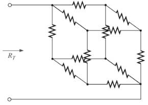
Fig. 7.89
Expert Solution & Answer
Want to see the full answer?
Check out a sample textbook solution
Students have asked these similar questions
A circuit consists of a series combination of 6.00 kΩ and5.00 kΩ resistors connected across a 50.0 V battery having negligibleinternal resistance. You want to measure the true potential difference(that is, the potential difference without the meter present) across the5.00 kΩ resistor using a voltmeter having an internal resistance of10.0 kΩ. By what percentage is the voltmeter reading in error from the true potential difference?
Four resistor of resistances 2 , 4 N, 6 N, and 8 0 are connected in series and a potential difference of 10 v is applies to the
circuit. What is the potential difference across the 8 Q resistor?
a) 2 V
b) 4 V
c) 6 V
d) 8 V
e) none of these
Determine the equivalent resistance between terminals a and b.
O 6.9130 Q
O 7.6547 Q
O 5.9253 Q
O 6.7520 Q
R1
ww
1 Ohm
R3
3 Ohms
R4
4 Ohms
ww
R2
ww
2 Ohms
R5
ww
5 Ohms
Chapter 7 Solutions
Introductory Circuit Analysis (13th Edition)
Ch. 7 - Which elements (individual elements, not...Ch. 7 - Repeat Problem 1 for the networks of Fig. 7.65....Ch. 7 - Determine RT for the networks in Fig. 7.66. Fig....Ch. 7 - Determine RT for the networks in Fig. 7.67. Fig....Ch. 7 - Find the total resistance for the configuration of...Ch. 7 - The total resistance RT for the network of Fig....Ch. 7 - For the network in Fig. 7.70. a. Does...Ch. 7 - For the network in Fig. 7.71: a. Determine RT. b....Ch. 7 - For the network of Fig. 7.72: a. find the currents...Ch. 7 - For the network of Fig. 7.73: Find the voltages V3...
Ch. 7 - For the network of Fig. 7.74 a. Find the voltages...Ch. 7 - For the circuit board in Fig. 7.75: Find the total...Ch. 7 - Find the value of each resistor for the network of...Ch. 7 - Find the resistance RT for the network of Fig....Ch. 7 - For the network in Fig. 7.78: a. Find currents...Ch. 7 - a. Find the magnitude and direction of the...Ch. 7 - Determine the currents I1andI2 for the network in...Ch. 7 - For the network in Fig. 7.81: a. Determine the...Ch. 7 - For the network in Fig. 7.82: a. Determine the...Ch. 7 - Determine the dc levels for the transistor network...Ch. 7 - For the network in Fig. 7.84: Determine the...Ch. 7 - For the network in Fig. 7.852 Determine RT by...Ch. 7 - For the network of Fig. 7.86: a. Find the voltages...Ch. 7 - For the network in Fig. 7.87: a. Determine the...Ch. 7 - For the network in Fig. 7.88 find the resistance...Ch. 7 - If all the resistors of the cube in Fig. 7.89 are...Ch. 7 - For the ladder network in Fig. 7.90: a. Find the...Ch. 7 - For the ladder network in Fig. 7.91: a. Determine...Ch. 7 - Given the voltage divider supply in Fig. 7.92: a....Ch. 7 - Determine the voltage divider supply resistors for...Ch. 7 - A studio lamp requires 40 V at 50 mA to burn...Ch. 7 - For the system in Fig. 7.94 a. At first exposure,...Ch. 7 - For the potentiometer in Fig. 7.95: a. What are...Ch. 7 - Prob. 34PCh. 7 - Given the voltmeter reading V = 27 V in Fig. 7.97...Ch. 7 - Determine the power delivered to the 6 load in...Ch. 7 - For the multiple ladder configuration in Fig....Ch. 7 - An iron-vane movement is rated 1 mA, 100 . a. What...Ch. 7 - Using a 50 A, 1000 movement, design a multirange...Ch. 7 - An iron-vane movement is rated 50 A , 1000 a....Ch. 7 - Using a 1 mA, 1000 movement, design a multirange...Ch. 7 - A digital meter has an internal resistance of 10 M...Ch. 7 - a. Design a series ohmmeter using a 100 A, 1000...Ch. 7 - Prob. 44PCh. 7 - Determine the reading of the ohmmeter for each...Ch. 7 - Using PSpice or Multisim, verify the result of...Ch. 7 - Using PSpice or Multisim, Confirm the solutions of...Ch. 7 - Using PSpice or Multisim, verify the result of...Ch. 7 - Using PSpice or Multisim, find voltage V6 of Fig....Ch. 7 - Using PSpice or Multisim, find voltages Vb and Vc...
Knowledge Booster


Learn more about
Need a deep-dive on the concept behind this application? Look no further. Learn more about this topic, electrical-engineering and related others by exploring similar questions and additional content below.Similar questions
- 7.48 What is the output voltage for the below circuit? V₁ = 40 mV V₂ = 20 mV 47 ΚΩ ww 4.7 ΚΩ ww 470 ΚΩ ww +12 V -12 Varrow_forwardA moving coil ammeter gives a full scale deflection for a current i = 250 mA and its coil has a resistance RC = 0.75 Ω. It is provided with a multiplier resistance Rm that allows a voltage measurement of up to 5 V. What is the value of the multiplier resistance?arrow_forwardFor the given circuit below find the power dissipated by resistor #7arrow_forward
- An AC electric motor is connected to a 240-V, 60-Hz source. A clamp-on ammeter with a peak hold function reveals that the motor has an inrush current of 34 A when the motor is first started. Your job is to reduce the inrush current to a value of 20 A by connecting a resistor in series with the motor. The resistor will be shunted out of the circuit after the motor is started. Using an ohmmeter, you find that the motor has a wire resistance of 3 . How much resistance should be connected in series with the motor to reduce the starting current to 20 A?arrow_forwardCalculate the RT for the following circuits and draw the equivalent circuits:arrow_forwardIn a PV Module,36 PV cells are connected in series. The size of each PV cell is 11cm x 8cm. The output current from the module is 3.33A and its efficiency is 15%. Estimate the Insolation(E) for this conditionarrow_forward
- Show all your solutionarrow_forwardA moving coil instrument gives full scale deflection with 15 mA. The resistance of coil is 5 Q. It is desired to convert this instrument into an ammeter to read up to 2 A. How to convert this instrument to read up to 30 V?arrow_forward+Vcc +15 V RL 100 N 1.0 kN 0.5 W C1 Vin 22 µF ing s RE1 8.2 N Vs 500 mV pp won tamR2 330 N 1.0 kHz RE2 36 N C2 100 µF 2. For the circuit in Figure 7-41, determine the following: (a) the power dissipated in the transistor with no load (b) the total power from the power supply with no load (c) the signal power in the load with a 500 mV inputarrow_forward
- INSTRUCTIONS: Solve the following problems. Show and COMPLETE solutions. Draw all CIRCUIT DIAGRAMS or the equivalent circuit (dummy circuit) as the case may be. Write your solutions on sheet/s of short bond paper. A battery is to consist of 20 identical cells. The emf of each cell is 1.5 V and the internal resistance is 0.20 ohm. This battery will be used to supply power to a 10 ohm lamp. Determine the current on the lamp if:1. The 20 cells are connected in series 2. The 20 cells are connected in parallel 3. The 20 cells are arranged 5 cells in series in 4 parallel rows.arrow_forwardExample-7 Thank youarrow_forward2. An Automatic Night Light uses a photocell to detect the amount of available light in a room. Under strong light the resistance of the photocell is 1kn but goes up to 100k2 in total darkness. The photocell is put in series with a 4.7k2 resistor so as to make a voltage divider when the ends are connected between +5V and GND as shown. As it gets darker in the room, the resistance of the photocell goes up and raises the voltage on the "Sensor Voltage" line. At "dusk", the photocell has a resistance of 10k2. Automatic Night Light 5v Vdd a. What will the range of the sensor voltage be as the photocell +5V goes from 1k2 (bright light) to 100k2 (total darkness)? Photocell b. Write the equation for VoUT expressed in terms of the op-amp Sensor Voltage LM358AD Vout U1A mmarceau 5V inputs and gain. What is the maximum range for Vour? Reference R4 24.7ka Voltage (V) White LED C. Assuming the light is to come on at "dusk", what must the POTENTIOMETER reference voltage be set to to have the LED…arrow_forward
arrow_back_ios
SEE MORE QUESTIONS
arrow_forward_ios
Recommended textbooks for you
 Delmar's Standard Textbook Of ElectricityElectrical EngineeringISBN:9781337900348Author:Stephen L. HermanPublisher:Cengage Learning
Delmar's Standard Textbook Of Electricity
Electrical Engineering
ISBN:9781337900348
Author:Stephen L. Herman
Publisher:Cengage Learning
Electrical Measuring Instruments - Testing Equipment Electrical - Types of Electrical Meters; Author: Learning Engineering;https://www.youtube.com/watch?v=gkeJzRrwe5k;License: Standard YouTube License, CC-BY
01 - Instantaneous Power in AC Circuit Analysis (Electrical Engineering); Author: Math and Science;https://www.youtube.com/watch?v=If25y4Nhvw4;License: Standard YouTube License, CC-BY