
Concept explainers
Videos
For the system in Fig. 7.94
a. At first exposure, does the design appear to be a good one?
b. In the absence of the 10 k
c. Determine the values of
= 3 V when the load is applied, and compare them to the results of part (b).
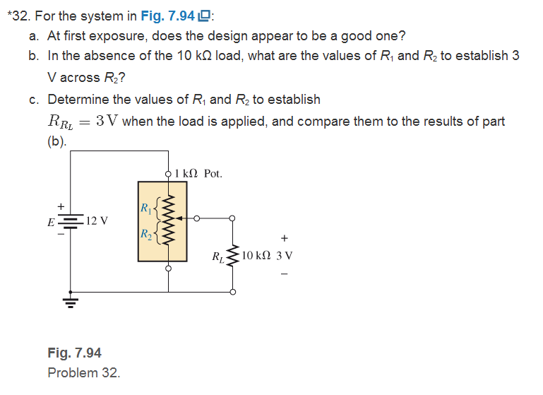
Fig. 7.94
Want to see the full answer?
Check out a sample textbook solution
Chapter 7 Solutions
Introductory Circuit Analysis (13th Edition)
Additional Engineering Textbook Solutions
Fundamentals of Applied Electromagnetics (7th Edition)
Loose Leaf for Engineering Circuit Analysis Format: Loose-leaf
ELECTRICITY FOR TRADES (LOOSELEAF)
Engineering Electromagnetics
Basic Engineering Circuit Analysis
Electric Motors and Control Systems


- 7.48 What is the output voltage for the below circuit? V₁ = 40 mV V₂ = 20 mV 47 ΚΩ ww 4.7 ΚΩ ww 470 ΚΩ ww +12 V -12 Varrow_forward7. using node analysis, find the voltage of each node and the current in the 4 ohms resistance 5 A U9 2 A USarrow_forwardConsider the following figure. 7.00 2 4.00 2 9.00 N R (a) Find the equivalent resistance between points a and b in the figure. (R = 11.0 n)arrow_forward
- +Vcc +15 V RL 100 N 1.0 kN 0.5 W C1 Vin 22 µF ing s RE1 8.2 N Vs 500 mV pp won tamR2 330 N 1.0 kHz RE2 36 N C2 100 µF 2. For the circuit in Figure 7-41, determine the following: (a) the power dissipated in the transistor with no load (b) the total power from the power supply with no load (c) the signal power in the load with a 500 mV inputarrow_forwardQuestion 7 Tough cookie for one point! :-) L1 R 1H 1kQ L2 600mH Not coupled coils 120VRMS 140 Hz What value of C will make the PF of this circuit 1? O 0.345 uF O 3.45 uF O 345 uF O 34.5 uF SAMSUNGarrow_forward7. A 400-N resistor is connected in series with a 2358 pF capacitor across a 12 V a.c. supply. Determine the supply frequency if the current flowing in the circuit is 24 mA.arrow_forward
- 7:35 l LTE O 1 Bartleby Done 22 of 22 Superposition is most applicable when a circuit contains which of the following? O A single current source. O No voltage or current sources. O A single voltage source. O Multiple voltage and current sources. !!arrow_forwardCalculate the RT for the following circuits and draw the equivalent circuits:arrow_forward7.48 What is the output voltage for the below circuit? 470 ΚΩ ww V₁ = 40 mV V₂ = 20 mV 47 ΚΩ ww 4.7 ΚΩ ww +12 V -12 V Earrow_forward
- A 750-ohm resistor, an uncharged 1.50 uF capacitor, and a 8.00-V emf are connected in series. (a) What is the current after one time constant? (b) What is the voltage on the capacitor after one time constant?arrow_forward10. Consider the electrical schematic of an automo- bile brake light shown in Fig. 7-56. Redesign the schematic to keep the remaining bulbs lit when one bulb burns out. Use one fuse for the entire system to protect from any circuit overloads. 12 VDC RIGHT-HAND LAMPS BRAKE PEDAL SWITCH LEFT-HAND LAMPS FUSE Fig. 7-56arrow_forwardAn alternating current bridge is arranged as follows: The arm BC and DA consists of non-inductive resistance of 800 Ω each. A balance is obtained when resistances of the arms DE and CD of non-inductive variable resistances of 200 Ω, 1k Ω respectively. The arm EC of a capacitor of 1 µF capacitance. The alternating current source is connected to A and C and the telephone receiver to B and E. Calculate the resistance and inductance of arm AB. Also find Q factor, when supply frequency is 1500Hz.arrow_forward
 Delmar's Standard Textbook Of ElectricityElectrical EngineeringISBN:9781337900348Author:Stephen L. HermanPublisher:Cengage Learning