
Introductory Circuit Analysis (13th Edition)
13th Edition
ISBN: 9780133923605
Author: Robert L. Boylestad
Publisher: PEARSON
expand_more
expand_more
format_list_bulleted
Concept explainers
Videos
Textbook Question
Chapter 7, Problem 14P
Find the resistance RT for the network of Fig. 7.77. Hint! If it was infinite in length, how would the resistance looking into the next vertical
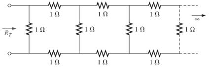
Fig. 7. 77
Expert Solution & Answer
Want to see the full answer?
Check out a sample textbook solution
Students have asked these similar questions
For the network of Fig. 7.86, Vp = 12 V. Determine:
a. Ip.
b. Vs and Vps-
c. Vg and VGs-
d. Vp.
18 V
2 k2
O Vp = 12 V
+
VG
12 VoMw
VDS
Ipss = 8 mA
680 k2
VGS
Vs
'110 k2
0.68 k2
Q 2)
For the network in Fig. 7.64:
a. Find the total resistance R,
b. Find the source current I, and currents /, and Iy.
c. Find current ls.
d. Find voltages V; and Va.
Ry
R
120
40
R4
14 V
V, R
120
Ry
1:0r 1%EM
とイ l
المكالمات
H.W -2
6. For the circuit board in Fig. 7.66:
a. Find the total resistance R, of the configuration.
b. Find the current drawn from the supply if the applied
voltage is 48 V.
c. Find the reading of the applied voltmeter.
6.8 kf2
V
3.3 kfl
2 k
Rr
1 k
-24 kf
48 V
FIG, 7,66
Problem 6.
Chapter 7 Solutions
Introductory Circuit Analysis (13th Edition)
Ch. 7 - Which elements (individual elements, not...Ch. 7 - Repeat Problem 1 for the networks of Fig. 7.65....Ch. 7 - Determine RT for the networks in Fig. 7.66. Fig....Ch. 7 - Determine RT for the networks in Fig. 7.67. Fig....Ch. 7 - Find the total resistance for the configuration of...Ch. 7 - The total resistance RT for the network of Fig....Ch. 7 - For the network in Fig. 7.70. a. Does...Ch. 7 - For the network in Fig. 7.71: a. Determine RT. b....Ch. 7 - For the network of Fig. 7.72: a. find the currents...Ch. 7 - For the network of Fig. 7.73: Find the voltages V3...
Ch. 7 - For the network of Fig. 7.74 a. Find the voltages...Ch. 7 - For the circuit board in Fig. 7.75: Find the total...Ch. 7 - Find the value of each resistor for the network of...Ch. 7 - Find the resistance RT for the network of Fig....Ch. 7 - For the network in Fig. 7.78: a. Find currents...Ch. 7 - a. Find the magnitude and direction of the...Ch. 7 - Determine the currents I1andI2 for the network in...Ch. 7 - For the network in Fig. 7.81: a. Determine the...Ch. 7 - For the network in Fig. 7.82: a. Determine the...Ch. 7 - Determine the dc levels for the transistor network...Ch. 7 - For the network in Fig. 7.84: Determine the...Ch. 7 - For the network in Fig. 7.852 Determine RT by...Ch. 7 - For the network of Fig. 7.86: a. Find the voltages...Ch. 7 - For the network in Fig. 7.87: a. Determine the...Ch. 7 - For the network in Fig. 7.88 find the resistance...Ch. 7 - If all the resistors of the cube in Fig. 7.89 are...Ch. 7 - For the ladder network in Fig. 7.90: a. Find the...Ch. 7 - For the ladder network in Fig. 7.91: a. Determine...Ch. 7 - Given the voltage divider supply in Fig. 7.92: a....Ch. 7 - Determine the voltage divider supply resistors for...Ch. 7 - A studio lamp requires 40 V at 50 mA to burn...Ch. 7 - For the system in Fig. 7.94 a. At first exposure,...Ch. 7 - For the potentiometer in Fig. 7.95: a. What are...Ch. 7 - Prob. 34PCh. 7 - Given the voltmeter reading V = 27 V in Fig. 7.97...Ch. 7 - Determine the power delivered to the 6 load in...Ch. 7 - For the multiple ladder configuration in Fig....Ch. 7 - An iron-vane movement is rated 1 mA, 100 . a. What...Ch. 7 - Using a 50 A, 1000 movement, design a multirange...Ch. 7 - An iron-vane movement is rated 50 A , 1000 a....Ch. 7 - Using a 1 mA, 1000 movement, design a multirange...Ch. 7 - A digital meter has an internal resistance of 10 M...Ch. 7 - a. Design a series ohmmeter using a 100 A, 1000...Ch. 7 - Prob. 44PCh. 7 - Determine the reading of the ohmmeter for each...Ch. 7 - Using PSpice or Multisim, verify the result of...Ch. 7 - Using PSpice or Multisim, Confirm the solutions of...Ch. 7 - Using PSpice or Multisim, verify the result of...Ch. 7 - Using PSpice or Multisim, find voltage V6 of Fig....Ch. 7 - Using PSpice or Multisim, find voltages Vb and Vc...
Additional Engineering Textbook Solutions
Find more solutions based on key concepts
With respect to the circuit in Fig. 5.90, (a) employ Thévenin’s theorem to determine the equivalent network see...
Loose Leaf for Engineering Circuit Analysis Format: Loose-leaf
Three point charges of equal magnitude q, that will yield a zero net electric field at the origin.
Engineering Electromagnetics
What is the color code for a 365- five-band precision resistor with a tolerance of 5 percent?
ELECTRICITY FOR TRADES (LOOSELEAF)
How many coulombs do 93.8 1016 electrons represent?
Principles Of Electric Circuits
Explain the main function of each of the following major components of a PLC: a. Processor module (CPU) b. I/O ...
Programmable Logic Controllers
Electric power systems provide energy in a variety of commercial and industrial settings. Make a list of system...
Principles and Applications of Electrical Engineering
Knowledge Booster


Learn more about
Need a deep-dive on the concept behind this application? Look no further. Learn more about this topic, electrical-engineering and related others by exploring similar questions and additional content below.Similar questions
- fig. 7.80 for the Gufiguration of © find the currents I2, Is andl Is 5 find the Joltages Vy and us Ri R3 Ru R6 Rs R7 Ri 302 32arrow_forward*11. For the series-parallel network of Fig. 7.74: R2 R6 a. Find the current I. b. Find the currents I and Ig. c. Find the current Ig. d. Find the voltage Vab 6Ω V 19 at Ro 60 1s R1 10 Ω 80 V 4Ω R = 40 Rs8N R20 FIG. 7.74 Problem 11.arrow_forward4_59407736683332... Problem II SERIES-PARALLEL NETWORKS *21. For the network of Fig. 7.84: a. Determine the current /. b. Calculate the open-circuit voltage V *22. For the network of Fig. 7.85, find the resistance current through it is 2 A. 20 V R E120 80 120 V 18 V 60 R200 30 FIG. 7.84 Problem 21. FIG. 7.85 Problem 22arrow_forward
- *21. For the network of Fig. 7.93, determine: a. Ipo and VGSo b. Vps and Vs. 18 V 2.2 k2 Ipss = 8 mA Vp = -8 V Vaso 0.39 k2 6-4 V FIG. 7.93 Problem 21.arrow_forwardPROBLE M 7.15 Determine VOUT versus vIN for the circuit shown in Figure 7.8 Assume that the MOSFET operates in saturation and is characterized by the paramete K and VT. What is the value of VOUT when VỊN = 0? PROBLEM 7.16 Determine vo versus vị for the circuit shown in Figure 7.8 Assume that the MOSFET operates in saturation and is characterized by the paramete K and VT. What is the value of vo when vj = = 0?arrow_forwardFET BIASING 33. For the network of Fig. 7.102, determine: a. Ip, and VGso' b. Vps- c. Vp. C9 9-16 V 2 k2 1 M2 VGs (Th) = -3 V Ip (on) = 4 mA VGs (on) = -7 V Vase FIG. 7.102arrow_forward
- 252 III SERIES-PARALLEL NETWORKS O +120 V *30. Determine the voltage divider supply resistors for the configuration of Fig. 7.93. Also determine the required wattage rating for each resistor, and compare their levels. 10 mA 20 mA R 100 V 40 mA 180 V 40 V 36 V 4 mA FIG. 7.93 Problem 30. CECTIarrow_forward23. For the voltage-divider configuration of Fig. 7.95, determine: a. Ipo and VGS b. VD and Vs. 9 24 V 2.2 ΚΩ LIDO 10 ΜΩ 6.8 ΜΩ www * VGSQ VGS(Th) = 3 V ID(on) = 5 mA VGS(on) = 6 V 0.75 ΚΩ FIG. 7.95 Problem 23.arrow_forward*25. For the combination network of Fig. 7.97, determine: a. VB and VG- b. Vg. c. IE, Ic, and Ip. d. Iв- e. Vc, Vs, and Vp- f. VCE- g. VDs- 2.2 k2 40 k2 OVD Dss 6 mA Vps Vp =-6 V Va.Va Vy.Vc le VCE B = 100 10 k2 VEE 1.2 k2 FIG. 7.97 Problem 25.arrow_forward
- 276 ||| SERIES-PARALLEL CIRCUITS *7. For the network in Fig. 7.67: a. Find currents I, I, and l b. Find voltages V, and V c. Find the power delivered to the 3 kfl resistor *& For the series-parallel configuration in Fig. 7.68 a. Find the source current , b. Find currents, and/ e. Find current l d. Find voltage V R₁1052 80 V = R₂ W 50 +20 V 50 592 w 4 R. 3802 ww 601 R₁4 R₁80 R, 212 + FIG. 7.68 Problem 8. FIG. 7.69 Problem 9. 9. Determine the currents /, and I, for the network in Fig. 7.69. 16 1 R₂ W www 250 12. For the network in Fig. 7.72: a. Determine the current 7. b. Calculate the currents I, and 1₂. e. Determine the voltage levels V, and V 8 20V M 8,30 [+ R₂30 R, GURGU FIG. 7.72 Problem 12. 48 V E = 28 V TOV R₂40 -79 R₂ *13. Determine the de levels for the transistor network in Fig. 7.73 using the fact that Vas-0.7 V, V-2V, and Ic - Ig That is a. Determine I, and lo -1k0 114 41242² FIG. 7.66 Problem 6 FIG. 7.67 Problem 7. R, 401 1₁ ly 4,340 R₂ 10. a. Find the magnitude and…arrow_forward14. For the network of Fig. 7.86, Vp = 12 V. Determine: a. Ip. b. Vs and Vps- c. Vg and VGs. d. Vp.arrow_forward. Determine Vp and VGs for the network of Fig. 7.91 using the provided information. VD 4 V 1.8 k2 1 k2 16 V o- VGS Dss= 4 mA Vp=-6 V 3.6 kn 1.2 kNarrow_forward
arrow_back_ios
SEE MORE QUESTIONS
arrow_forward_ios
Recommended textbooks for you
 Introductory Circuit Analysis (13th Edition)Electrical EngineeringISBN:9780133923605Author:Robert L. BoylestadPublisher:PEARSON
 Delmar's Standard Textbook Of ElectricityElectrical EngineeringISBN:9781337900348Author:Stephen L. HermanPublisher:Cengage Learning
 Programmable Logic ControllersElectrical EngineeringISBN:9780073373843Author:Frank D. PetruzellaPublisher:McGraw-Hill Education
 Fundamentals of Electric CircuitsElectrical EngineeringISBN:9780078028229Author:Charles K Alexander, Matthew SadikuPublisher:McGraw-Hill Education
 Electric Circuits. (11th Edition)Electrical EngineeringISBN:9780134746968Author:James W. Nilsson, Susan RiedelPublisher:PEARSON
 Engineering ElectromagneticsElectrical EngineeringISBN:9780078028151Author:Hayt, William H. (william Hart), Jr, BUCK, John A.Publisher:Mcgraw-hill Education,
Introductory Circuit Analysis (13th Edition)
Electrical Engineering
ISBN:9780133923605
Author:Robert L. Boylestad
Publisher:PEARSON
Delmar's Standard Textbook Of Electricity
Electrical Engineering
ISBN:9781337900348
Author:Stephen L. Herman
Publisher:Cengage Learning
Programmable Logic Controllers
Electrical Engineering
ISBN:9780073373843
Author:Frank D. Petruzella
Publisher:McGraw-Hill Education
Fundamentals of Electric Circuits
Electrical Engineering
ISBN:9780078028229
Author:Charles K Alexander, Matthew Sadiku
Publisher:McGraw-Hill Education
Electric Circuits. (11th Edition)
Electrical Engineering
ISBN:9780134746968
Author:James W. Nilsson, Susan Riedel
Publisher:PEARSON
Engineering Electromagnetics
Electrical Engineering
ISBN:9780078028151
Author:Hayt, William H. (william Hart), Jr, BUCK, John A.
Publisher:Mcgraw-hill Education,
Electrical Measuring Instruments - Testing Equipment Electrical - Types of Electrical Meters; Author: Learning Engineering;https://www.youtube.com/watch?v=gkeJzRrwe5k;License: Standard YouTube License, CC-BY
01 - Instantaneous Power in AC Circuit Analysis (Electrical Engineering); Author: Math and Science;https://www.youtube.com/watch?v=If25y4Nhvw4;License: Standard YouTube License, CC-BY