
Introductory Circuit Analysis (13th Edition)
13th Edition
ISBN: 9780133923605
Author: Robert L. Boylestad
Publisher: PEARSON
expand_more
expand_more
format_list_bulleted
Concept explainers
Videos
Textbook Question
thumb_up100%
Chapter 7, Problem 8P
For the network in Fig. 7.71:
a. Determine RT.
b. Find Is, I1 and I2.
c. Find voltage V8
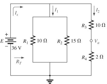
Fig. 7.71
Expert Solution & Answer

Trending nowThis is a popular solution!

Learn your wayIncludes step-by-step video

schedule04:01
Students have asked these similar questions
For the network of Fig. 7.91, VD 9 V. Determine:to.
a. ID.b. VS and VDS.c. VG and VGS.d. VP.
14. For the network of Fig. 7.86, Vp = 12 V. Determine:
a. Ip.
b. Vs and Vps-
c. Vg and VGs.
d. Vp.
Q 2)
For the network in Fig. 7.64:
a. Find the total resistance R,
b. Find the source current I, and currents /, and Iy.
c. Find current ls.
d. Find voltages V; and Va.
Ry
R
120
40
R4
14 V
V, R
120
Ry
Chapter 7 Solutions
Introductory Circuit Analysis (13th Edition)
Ch. 7 - Which elements (individual elements, not...Ch. 7 - Repeat Problem 1 for the networks of Fig. 7.65....Ch. 7 - Determine RT for the networks in Fig. 7.66. Fig....Ch. 7 - Determine RT for the networks in Fig. 7.67. Fig....Ch. 7 - Find the total resistance for the configuration of...Ch. 7 - The total resistance RT for the network of Fig....Ch. 7 - For the network in Fig. 7.70. a. Does...Ch. 7 - For the network in Fig. 7.71: a. Determine RT. b....Ch. 7 - For the network of Fig. 7.72: a. find the currents...Ch. 7 - For the network of Fig. 7.73: Find the voltages V3...
Ch. 7 - For the network of Fig. 7.74 a. Find the voltages...Ch. 7 - For the circuit board in Fig. 7.75: Find the total...Ch. 7 - Find the value of each resistor for the network of...Ch. 7 - Find the resistance RT for the network of Fig....Ch. 7 - For the network in Fig. 7.78: a. Find currents...Ch. 7 - a. Find the magnitude and direction of the...Ch. 7 - Determine the currents I1andI2 for the network in...Ch. 7 - For the network in Fig. 7.81: a. Determine the...Ch. 7 - For the network in Fig. 7.82: a. Determine the...Ch. 7 - Determine the dc levels for the transistor network...Ch. 7 - For the network in Fig. 7.84: Determine the...Ch. 7 - For the network in Fig. 7.852 Determine RT by...Ch. 7 - For the network of Fig. 7.86: a. Find the voltages...Ch. 7 - For the network in Fig. 7.87: a. Determine the...Ch. 7 - For the network in Fig. 7.88 find the resistance...Ch. 7 - If all the resistors of the cube in Fig. 7.89 are...Ch. 7 - For the ladder network in Fig. 7.90: a. Find the...Ch. 7 - For the ladder network in Fig. 7.91: a. Determine...Ch. 7 - Given the voltage divider supply in Fig. 7.92: a....Ch. 7 - Determine the voltage divider supply resistors for...Ch. 7 - A studio lamp requires 40 V at 50 mA to burn...Ch. 7 - For the system in Fig. 7.94 a. At first exposure,...Ch. 7 - For the potentiometer in Fig. 7.95: a. What are...Ch. 7 - Prob. 34PCh. 7 - Given the voltmeter reading V = 27 V in Fig. 7.97...Ch. 7 - Determine the power delivered to the 6 load in...Ch. 7 - For the multiple ladder configuration in Fig....Ch. 7 - An iron-vane movement is rated 1 mA, 100 . a. What...Ch. 7 - Using a 50 A, 1000 movement, design a multirange...Ch. 7 - An iron-vane movement is rated 50 A , 1000 a....Ch. 7 - Using a 1 mA, 1000 movement, design a multirange...Ch. 7 - A digital meter has an internal resistance of 10 M...Ch. 7 - a. Design a series ohmmeter using a 100 A, 1000...Ch. 7 - Prob. 44PCh. 7 - Determine the reading of the ohmmeter for each...Ch. 7 - Using PSpice or Multisim, verify the result of...Ch. 7 - Using PSpice or Multisim, Confirm the solutions of...Ch. 7 - Using PSpice or Multisim, verify the result of...Ch. 7 - Using PSpice or Multisim, find voltage V6 of Fig....Ch. 7 - Using PSpice or Multisim, find voltages Vb and Vc...
Additional Engineering Textbook Solutions
Find more solutions based on key concepts
Determine the capacitor voltage, power, and stored energy at t = 20 ms in the circuit ofFigure P3.12 Figure P3....
Electrical Engineering: Principles & Applications (7th Edition)
The switch in the bottom loop of Fig. P6.1 is closed at t = 0 and then opened at a later time t1. What is the d...
Fundamentals of Applied Electromagnetics (7th Edition)
What are the two primary stack operations? Describe them both.
Starting Out with C++ from Control Structures to Objects (8th Edition)
Type in and run the program presented in this chapter. Check the programs results by comparing the original fil...
Programming in C
For the class Craps in Fig. 6.8, state the scope of each of the following entities: the variable randomNumbers.
Java How To Program (Early Objects)
Every Java application program must have __________. a) a method named main b) more than one class definition c...
Starting Out with Java: From Control Structures through Objects (6th Edition)
Knowledge Booster


Learn more about
Need a deep-dive on the concept behind this application? Look no further. Learn more about this topic, electrical-engineering and related others by exploring similar questions and additional content below.Similar questions
- 11. For the series-parallel network of Fig. 7.59: a. Find the current I. R2 9. b. Find the currents I3 and I9. c. Find the current Ig. d. Find the voltage V. 50 V. R31 ab. R7 R,10 0 80 V R9 R4 = 42- R58N FIG. 7.59 Problem 11.arrow_forwardFor the network of Fig. 7.86, Vp = 12 V. Determine: a. Ip. b. Vs and Vps- c. Vg and VGs- d. Vp. 18 V 2 k2 O Vp = 12 V + VG 12 VoMw VDS Ipss = 8 mA 680 k2 VGS Vs '110 k2 0.68 k2arrow_forward4_59407736683332... Problem II SERIES-PARALLEL NETWORKS *21. For the network of Fig. 7.84: a. Determine the current /. b. Calculate the open-circuit voltage V *22. For the network of Fig. 7.85, find the resistance current through it is 2 A. 20 V R E120 80 120 V 18 V 60 R200 30 FIG. 7.84 Problem 21. FIG. 7.85 Problem 22arrow_forward
- 1:0r 1%EM とイ l المكالمات H.W -2 6. For the circuit board in Fig. 7.66: a. Find the total resistance R, of the configuration. b. Find the current drawn from the supply if the applied voltage is 48 V. c. Find the reading of the applied voltmeter. 6.8 kf2 V 3.3 kfl 2 k Rr 1 k -24 kf 48 V FIG, 7,66 Problem 6.arrow_forwardFor the ladder network in fig . 7.90 A. Find the current I B.Find the current I7 C.determine the voltage V3 V5 and V7 D. Calculate the power delivered to R7 and compare it to the power delivered by the 240 V supplyarrow_forward4. ror une network in Fig. 7.64: a. Find the total resistance RT. b. Find the source current I, and currents I, and I3. c. Find current Iş. d. Find voltages V2 and V4. 13 R3 R1 12 N R4 4Ω + 12 0 E 14 V V2 R2 60 V4 RT + +arrow_forward
- Question 7.31 For the network of Fig. 7.105, determine:a. IDQ and VGSQ.b.VDS.c. VD. .arrow_forward3. For the network of Fig. 7.85 , determine: a. VG. b. ID and VGS. c. VD and VS. d. VDS. O 20 V 2.2 kn 910 kQ Dss = 10 mA V, =-3.5 V Vasa 110 kQ 1.1 kaarrow_forward9. For the network of Fig. 7.57: a. Determine the current I,. b. Calculate the currents I2 and I3. c. Determine the voltage levels V, and V. Eo 20 V RI3N OVa 12 R2 3 2 R432 13 R5 R3 FIG. 7.57 Problem 9.arrow_forward
- *25. For the combination network of Fig. 7.97, determine: a. VB and VG- b. Vg. c. IE, Ic, and Ip. d. Iв- e. Vc, Vs, and Vp- f. VCE- g. VDs- 2.2 k2 40 k2 OVD Dss 6 mA Vps Vp =-6 V Va.Va Vy.Vc le VCE B = 100 10 k2 VEE 1.2 k2 FIG. 7.97 Problem 25.arrow_forward276 ||| SERIES-PARALLEL CIRCUITS *7. For the network in Fig. 7.67: a. Find currents I, I, and l b. Find voltages V, and V c. Find the power delivered to the 3 kfl resistor *& For the series-parallel configuration in Fig. 7.68 a. Find the source current , b. Find currents, and/ e. Find current l d. Find voltage V R₁1052 80 V = R₂ W 50 +20 V 50 592 w 4 R. 3802 ww 601 R₁4 R₁80 R, 212 + FIG. 7.68 Problem 8. FIG. 7.69 Problem 9. 9. Determine the currents /, and I, for the network in Fig. 7.69. 16 1 R₂ W www 250 12. For the network in Fig. 7.72: a. Determine the current 7. b. Calculate the currents I, and 1₂. e. Determine the voltage levels V, and V 8 20V M 8,30 [+ R₂30 R, GURGU FIG. 7.72 Problem 12. 48 V E = 28 V TOV R₂40 -79 R₂ *13. Determine the de levels for the transistor network in Fig. 7.73 using the fact that Vas-0.7 V, V-2V, and Ic - Ig That is a. Determine I, and lo -1k0 114 41242² FIG. 7.66 Problem 6 FIG. 7.67 Problem 7. R, 401 1₁ ly 4,340 R₂ 10. a. Find the magnitude and…arrow_forwardCH. 7 6. For the circuit board in Fig. 7.66: a. Find the total resistance R, of the configuration. Ans. R¡ = 0.8 k2 b. Find the current drawn from the supply if the applied voltage is 48 V. Ans. Is 60 mA c. Find the reading of the applied voltmeter. Ans. V 19.2 V 6.8 k2 1.2 kfl 3.3 kf 2 kf2 RT 48 V 2.4 kfarrow_forward
arrow_back_ios
SEE MORE QUESTIONS
arrow_forward_ios
Recommended textbooks for you
 Introductory Circuit Analysis (13th Edition)Electrical EngineeringISBN:9780133923605Author:Robert L. BoylestadPublisher:PEARSON
 Delmar's Standard Textbook Of ElectricityElectrical EngineeringISBN:9781337900348Author:Stephen L. HermanPublisher:Cengage Learning
 Programmable Logic ControllersElectrical EngineeringISBN:9780073373843Author:Frank D. PetruzellaPublisher:McGraw-Hill Education
 Fundamentals of Electric CircuitsElectrical EngineeringISBN:9780078028229Author:Charles K Alexander, Matthew SadikuPublisher:McGraw-Hill Education
 Electric Circuits. (11th Edition)Electrical EngineeringISBN:9780134746968Author:James W. Nilsson, Susan RiedelPublisher:PEARSON
 Engineering ElectromagneticsElectrical EngineeringISBN:9780078028151Author:Hayt, William H. (william Hart), Jr, BUCK, John A.Publisher:Mcgraw-hill Education,
Introductory Circuit Analysis (13th Edition)
Electrical Engineering
ISBN:9780133923605
Author:Robert L. Boylestad
Publisher:PEARSON
Delmar's Standard Textbook Of Electricity
Electrical Engineering
ISBN:9781337900348
Author:Stephen L. Herman
Publisher:Cengage Learning
Programmable Logic Controllers
Electrical Engineering
ISBN:9780073373843
Author:Frank D. Petruzella
Publisher:McGraw-Hill Education
Fundamentals of Electric Circuits
Electrical Engineering
ISBN:9780078028229
Author:Charles K Alexander, Matthew Sadiku
Publisher:McGraw-Hill Education
Electric Circuits. (11th Edition)
Electrical Engineering
ISBN:9780134746968
Author:James W. Nilsson, Susan Riedel
Publisher:PEARSON
Engineering Electromagnetics
Electrical Engineering
ISBN:9780078028151
Author:Hayt, William H. (william Hart), Jr, BUCK, John A.
Publisher:Mcgraw-hill Education,
Current Divider Rule; Author: Neso Academy;https://www.youtube.com/watch?v=hRU1mKWUehY;License: Standard YouTube License, CC-BY