
Introductory Circuit Analysis (13th Edition)
13th Edition
ISBN: 9780133923605
Author: Robert L. Boylestad
Publisher: PEARSON
expand_more
expand_more
format_list_bulleted
Concept explainers
Videos
Textbook Question
Chapter 7, Problem 12P
For the circuit board in Fig. 7.75:
- Find the total resistance RT of the configuration.
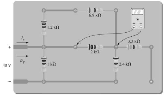
Fig. 7.75
b. Find the current drawn from the supply if the applied voltage is 48 V.
c. Find the reading of the applied voltmeter.
Expert Solution & Answer
Want to see the full answer?
Check out a sample textbook solution
Students have asked these similar questions
The load across a 50.0-V battery consists of a series combination of two lamps with
resistances of 125 ohms and 225 ohms.
a. Find the total resistance of the circuit.
b. Find the current in the circuit.
c. Find the potential difference across the 125- ohm lamp.
Two voltmeter of (0-300 V) range are connected in parallel to a A.C. circuit. One voltmeter is moving iron type reads 200 V. If the other is PMMC instrument, its reading will be
a)200 V b) slightly less than 200 V c) 0 V
Calculate the Equivalent resistance Rab
Chapter 7 Solutions
Introductory Circuit Analysis (13th Edition)
Ch. 7 - Which elements (individual elements, not...Ch. 7 - Repeat Problem 1 for the networks of Fig. 7.65....Ch. 7 - Determine RT for the networks in Fig. 7.66. Fig....Ch. 7 - Determine RT for the networks in Fig. 7.67. Fig....Ch. 7 - Find the total resistance for the configuration of...Ch. 7 - The total resistance RT for the network of Fig....Ch. 7 - For the network in Fig. 7.70. a. Does...Ch. 7 - For the network in Fig. 7.71: a. Determine RT. b....Ch. 7 - For the network of Fig. 7.72: a. find the currents...Ch. 7 - For the network of Fig. 7.73: Find the voltages V3...
Ch. 7 - For the network of Fig. 7.74 a. Find the voltages...Ch. 7 - For the circuit board in Fig. 7.75: Find the total...Ch. 7 - Find the value of each resistor for the network of...Ch. 7 - Find the resistance RT for the network of Fig....Ch. 7 - For the network in Fig. 7.78: a. Find currents...Ch. 7 - a. Find the magnitude and direction of the...Ch. 7 - Determine the currents I1andI2 for the network in...Ch. 7 - For the network in Fig. 7.81: a. Determine the...Ch. 7 - For the network in Fig. 7.82: a. Determine the...Ch. 7 - Determine the dc levels for the transistor network...Ch. 7 - For the network in Fig. 7.84: Determine the...Ch. 7 - For the network in Fig. 7.852 Determine RT by...Ch. 7 - For the network of Fig. 7.86: a. Find the voltages...Ch. 7 - For the network in Fig. 7.87: a. Determine the...Ch. 7 - For the network in Fig. 7.88 find the resistance...Ch. 7 - If all the resistors of the cube in Fig. 7.89 are...Ch. 7 - For the ladder network in Fig. 7.90: a. Find the...Ch. 7 - For the ladder network in Fig. 7.91: a. Determine...Ch. 7 - Given the voltage divider supply in Fig. 7.92: a....Ch. 7 - Determine the voltage divider supply resistors for...Ch. 7 - A studio lamp requires 40 V at 50 mA to burn...Ch. 7 - For the system in Fig. 7.94 a. At first exposure,...Ch. 7 - For the potentiometer in Fig. 7.95: a. What are...Ch. 7 - Prob. 34PCh. 7 - Given the voltmeter reading V = 27 V in Fig. 7.97...Ch. 7 - Determine the power delivered to the 6 load in...Ch. 7 - For the multiple ladder configuration in Fig....Ch. 7 - An iron-vane movement is rated 1 mA, 100 . a. What...Ch. 7 - Using a 50 A, 1000 movement, design a multirange...Ch. 7 - An iron-vane movement is rated 50 A , 1000 a....Ch. 7 - Using a 1 mA, 1000 movement, design a multirange...Ch. 7 - A digital meter has an internal resistance of 10 M...Ch. 7 - a. Design a series ohmmeter using a 100 A, 1000...Ch. 7 - Prob. 44PCh. 7 - Determine the reading of the ohmmeter for each...Ch. 7 - Using PSpice or Multisim, verify the result of...Ch. 7 - Using PSpice or Multisim, Confirm the solutions of...Ch. 7 - Using PSpice or Multisim, verify the result of...Ch. 7 - Using PSpice or Multisim, find voltage V6 of Fig....Ch. 7 - Using PSpice or Multisim, find voltages Vb and Vc...
Additional Engineering Textbook Solutions
Find more solutions based on key concepts
Does the severity of an electric shock increase ordecrease with eh of the following changes? a. A decrease in t...
Electric Motors and Control Systems
When travelers from the USA and Canada visit Europe, they encounter a different power distribution system. Wall...
Electric machinery fundamentals
Explain the main function of each of the following major components of a PLC: a. Processor module (CPU) b. I/O ...
Programmable Logic Controllers
Find I0 and I1 in the circuit in Fig.P2.12.
Basic Engineering Circuit Analysis
How many coulombs do 93.8 1016 electrons represent?
Principles Of Electric Circuits
The voltage source of the circuit shown in Fig. P1.29 is given by s(t)=25cos(4104t45)(V). Obtain an expression ...
Fundamentals of Applied Electromagnetics (7th Edition)
Knowledge Booster


Learn more about
Need a deep-dive on the concept behind this application? Look no further. Learn more about this topic, electrical-engineering and related others by exploring similar questions and additional content below.Similar questions
- The load across a 50.0-V battery consists of a series combination of two lamps with resistances of 125 $2 Dand 225 N. a. Find the total resistance of the circuit. b. Find the current in the circuit. c. Find the potential difference across the 125-2 Olamp. 21 2, and 15. The load across a 12-V battery consists of a series combination of three resistances are 15 2, 24 N, respectively. a. Draw the circuit diagram. b. What is the total resistance of the load? c. What is the magnitude of the circuit current?arrow_forwardQ: A wood panel containing 16 solar cells. Calculate the total open circuit voltage and short circuit current coming out of the board and draw the relationship between current and voltages in the following cases 1- If you connect each two cells in series and connect the groups in parallel. 2- If all four cells are connected in parallel and the groups are linked in succession, noting that each cell has the following characteristics: Vos = 0.75V, Isc = 2 mAarrow_forwardHow can you explain scientifically the generation of high voltage to feed the ignition plugs in car engine about 11KV while the voltage source is a battery 12Varrow_forward
- Figure 1 shows the circuit diagram of an automotive lighting system, and all lamps has 500 Q resistance. 3. a) Describe the characteristics of a parallel circuit in terms of resistance current and voltage. b) Determine: The current generated by the battery if the brake switch is closed The current generated by the battery if the light switch is closed iii. The current generated by the battery if the light switch and high-beam switch are closed i. i. iv. The current generated by the battery if all switches are closed high-beam switch Lights switch Brake switch Right Left Right Left Right Left Right Left Low-beam Brake lights High-beam headlights Tailights headlights 12V Figure 1arrow_forwarddocs.google.com 8 1. What are the values of the resistances bellow according to these colors? a. Orange – blue - green - gold b. Violet – yellow – violet – silver c. Yellow – gray - green - orange - gold d. Blue - brown- red- orange - gold – red 1 Add file 2. How can you connect Avometer to measure current, voltage and resistance? * Your answer 3- how can you examine the capacitor and diode if they work or not ? *arrow_forwardTwo practical batteries are connected in series, such that the positive terminal of one battery is connected to the positive terminal of the other battery. Which of the following must be true? OA. The total EMF is greater than the individual EMFS of the battery O B. When the series combination of batteries is connected to a load, the current will be uneven throughout the circuit. O C. The total internal resistance is equal to the sum of the individual internal resistances O D. When the series combination of batteries is connected to a load, both batteries will be discharging.arrow_forward
- Calculate the total resistance RT.arrow_forward7. A 100 W incandescent lamp has a resistance when cold (lamp extinguished) that is only 1/12 of its hot (lamp illuminated) resistance value. a) What is the lamp current and its hot resistance when placed across a 120 V line? b) What is the cold resistance of this lamp? c) What is the instantaneous current through the lamp at the moment it is switched on? d) What power does the lamp dissipate at this instant?arrow_forwardvoltmeter is connected in series on the element when we are taking the reading of the voltage Select the correct response: True Falsearrow_forward
- A permanent - magnet moving coil instrument gives full - scale reading of 25 mA when a p.d.across its terminals is 75 m V.Show how it can be used (1)asan ammeter for a range of 0 -100A (ii )asa voltmeter for a range of 0 - 750 V.Also find the multiplyingarrow_forward1. The no-load terminal voltage of a battery is 30 V. The terminal voltage drops to 22 V when supplying a current of 5 A. Determine the emf and the internal resistance of this battery. 2. Two identical zinc carbon batteries are available. When connected in series, they supply 0.5 A to a 4 ohm resistor. When connected in parallel, they supply 0.4 A to a 5 ohm resistor. Determine the emf and internal resistance of each battery. 3. When supplying a current of 5 A, the terminal voltage of a battery is 15 V. The battery is then recharged at a rate of 3 A and the terminal voltage is found to be 21 V. Determine the emf and the internal resistance of the battery. 4. A battery with an emf of 12 V and an internal resistance of 0.8 ohm is to be recharged through a 20 V source. (a) show by means of a diagram the connection of the circuit elements. (b) What is the current in the circuit? (c) The recharging current is to be limited to 3 A. What is the value of the limiting…arrow_forward0.2 A moving coil instrument gives a half scale deflection for a current of 20 mA with a potential difference of 300 mV across it. Using direct method, calculate and design: i) Shunt resistors are required to use it as an ammeter to get ranges 0 – 50 A and 0- 100 A. ii) Multiplier resistors are required to use it as a voltmeter of ranges 0 – 150 V and 0– 300 v.arrow_forward
arrow_back_ios
SEE MORE QUESTIONS
arrow_forward_ios
Recommended textbooks for you
 Introductory Circuit Analysis (13th Edition)Electrical EngineeringISBN:9780133923605Author:Robert L. BoylestadPublisher:PEARSON
 Delmar's Standard Textbook Of ElectricityElectrical EngineeringISBN:9781337900348Author:Stephen L. HermanPublisher:Cengage Learning
 Programmable Logic ControllersElectrical EngineeringISBN:9780073373843Author:Frank D. PetruzellaPublisher:McGraw-Hill Education
 Fundamentals of Electric CircuitsElectrical EngineeringISBN:9780078028229Author:Charles K Alexander, Matthew SadikuPublisher:McGraw-Hill Education
 Electric Circuits. (11th Edition)Electrical EngineeringISBN:9780134746968Author:James W. Nilsson, Susan RiedelPublisher:PEARSON
 Engineering ElectromagneticsElectrical EngineeringISBN:9780078028151Author:Hayt, William H. (william Hart), Jr, BUCK, John A.Publisher:Mcgraw-hill Education,
Introductory Circuit Analysis (13th Edition)
Electrical Engineering
ISBN:9780133923605
Author:Robert L. Boylestad
Publisher:PEARSON
Delmar's Standard Textbook Of Electricity
Electrical Engineering
ISBN:9781337900348
Author:Stephen L. Herman
Publisher:Cengage Learning
Programmable Logic Controllers
Electrical Engineering
ISBN:9780073373843
Author:Frank D. Petruzella
Publisher:McGraw-Hill Education
Fundamentals of Electric Circuits
Electrical Engineering
ISBN:9780078028229
Author:Charles K Alexander, Matthew Sadiku
Publisher:McGraw-Hill Education
Electric Circuits. (11th Edition)
Electrical Engineering
ISBN:9780134746968
Author:James W. Nilsson, Susan Riedel
Publisher:PEARSON
Engineering Electromagnetics
Electrical Engineering
ISBN:9780078028151
Author:Hayt, William H. (william Hart), Jr, BUCK, John A.
Publisher:Mcgraw-hill Education,
Current Divider Rule; Author: Neso Academy;https://www.youtube.com/watch?v=hRU1mKWUehY;License: Standard YouTube License, CC-BY