
Videos
For the potentiometer in Fig. 7.95:
a. What are the voltages Vab and Vbc with no load applied
b. What are the voltages
c. What is the power dissipated by the potentiometer under the loaded conditions in Fig. 7.95?
d. What is the power dissipated by the potentiometer with no loads applied? Compare it to the results of part (c).
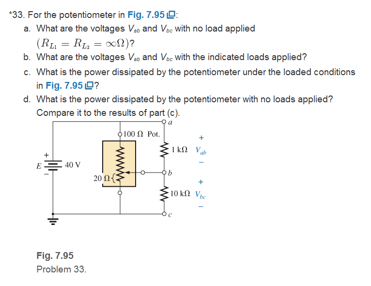
Fig. 7.95
Want to see the full answer?
Check out a sample textbook solution
Chapter 7 Solutions
Introductory Circuit Analysis (13th Edition)
Additional Engineering Textbook Solutions
Electric Motors and Control Systems
Electric Circuits. (11th Edition)
Electric machinery fundamentals
Electronics Fundamentals: Circuits, Devices & Applications
Principles Of Electric Circuits
Basic Engineering Circuit Analysis


- Exercice 60: In Figure 7.92, the ammeter reads 2.0 A and the volmeter reads 2.0 V. Use this information to find the value of the unknown resistance R as well as the currents I1 and I2. The potential at the terminal of measuring devices identified by a + is higher than the potential at the terminal identified by a -. Answer: R= 3.00 Ohms, I1 = 2.00 A, I2= 4.00 A Please show steps, formulas and explanations for my own understandingarrow_forward7.48 What is the output voltage for the below circuit? 470 ΚΩ ww V₁ = 40 mV V₂ = 20 mV 47 ΚΩ ww 4.7 ΚΩ ww +12 V -12 V Earrow_forwardPlease clarify and find the correct solution on how to get the equivalent voltage in this problem.arrow_forward
- a utility company plans to connect a total of 20 uf of capacitance to a 7200 v line at 60 hertz to make this connection the capacitors will be connected in series what is the capacitance of each capacitor what is the minimu ac voltage of each capacitor what is the current flow of the circuit and what is the kvar rating of each capacitor.arrow_forwardINSTRUCTIONS: Solve the following problems. Show and COMPLETE solutions. Draw all CIRCUIT DIAGRAMS or the equivalent circuit (dummy circuit) as the case may be. Write your solutions on sheet/s of short bond paper. A battery is to consist of 20 identical cells. The emf of each cell is 1.5 V and the internal resistance is 0.20 ohm. This battery will be used to supply power to a 10 ohm lamp. Determine the current on the lamp if:1. The 20 cells are connected in series 2. The 20 cells are connected in parallel 3. The 20 cells are arranged 5 cells in series in 4 parallel rows.arrow_forwardCalculate the RT for the following circuits and draw the equivalent circuits:arrow_forward
- 32 12 VFRT→ 162 12 2 Figure 7.1 See Figure 7.1. What is the current through the 30 resistor? 1.33 A 0.33 A 2.0 A O 1.0 Aarrow_forwardA circuit consists of a series combination of 6.00 kΩ and5.00 kΩ resistors connected across a 50.0 V battery having negligibleinternal resistance. You want to measure the true potential difference(that is, the potential difference without the meter present) across the5.00 kΩ resistor using a voltmeter having an internal resistance of10.0 kΩ. By what percentage is the voltmeter reading in error from the true potential difference?arrow_forward3. A 45 uF capacitor and a 30 uF capacitor are connected in parallel to a 25 V battery. What is the total capacitance of the circuit? b. What is the voltage, V, across capacitor, C,? c. What is the voltage, V, across capacitor, C? d. How much charge, Q, is on capacitor, C,? How much charge, Q2, is on capacitor, C,? a. e.arrow_forward
- Consider the following figure. 7.00 2 4.00 2 9.00 N R (a) Find the equivalent resistance between points a and b in the figure. (R = 11.0 n)arrow_forwardQuestion 7 Tough cookie for one point! :-) L1 R 1H 1kQ L2 600mH Not coupled coils 120VRMS 140 Hz What value of C will make the PF of this circuit 1? O 0.345 uF O 3.45 uF O 345 uF O 34.5 uF SAMSUNGarrow_forwardAn AC electric motor is connected to a 240-V, 60-Hz source. A clamp-on ammeter with a peak hold function reveals that the motor has an inrush current of 34 A when the motor is first started. Your job is to reduce the inrush current to a value of 20 A by connecting a resistor in series with the motor. The resistor will be shunted out of the circuit after the motor is started. Using an ohmmeter, you find that the motor has a wire resistance of 3 . How much resistance should be connected in series with the motor to reduce the starting current to 20 A?arrow_forward
 Delmar's Standard Textbook Of ElectricityElectrical EngineeringISBN:9781337900348Author:Stephen L. HermanPublisher:Cengage Learning