
Introductory Circuit Analysis (13th Edition)
13th Edition
ISBN: 9780133923605
Author: Robert L. Boylestad
Publisher: PEARSON
expand_more
expand_more
format_list_bulleted
Concept explainers
Videos
Textbook Question
Chapter 7, Problem 23P
For the network of Fig. 7.86:
a. Find the voltages
b. Calculate the current
c. Determine the voltage
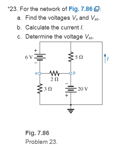
Fig. 7.86
Expert Solution & Answer
Want to see the full answer?
Check out a sample textbook solution
Students have asked these similar questions
Q1: If the input x[n] = [001111] is applied to a discrete-time LTI system of impulse response
h[n] = [321]. Using z-transform, find the output y[n] of the system.
Q1: If the input x[n] = [001111] is applied to a discrete-time LTI system of impulse response
h[n]=
= [321]. Find the output y[n] of the system.
a. Using analytical technique.
b. Using linear convolution technique.
Don't use ai to answer I will report you answer
Chapter 7 Solutions
Introductory Circuit Analysis (13th Edition)
Ch. 7 - Which elements (individual elements, not...Ch. 7 - Repeat Problem 1 for the networks of Fig. 7.65....Ch. 7 - Determine RT for the networks in Fig. 7.66. Fig....Ch. 7 - Determine RT for the networks in Fig. 7.67. Fig....Ch. 7 - Find the total resistance for the configuration of...Ch. 7 - The total resistance RT for the network of Fig....Ch. 7 - For the network in Fig. 7.70. a. Does...Ch. 7 - For the network in Fig. 7.71: a. Determine RT. b....Ch. 7 - For the network of Fig. 7.72: a. find the currents...Ch. 7 - For the network of Fig. 7.73: Find the voltages V3...
Ch. 7 - For the network of Fig. 7.74 a. Find the voltages...Ch. 7 - For the circuit board in Fig. 7.75: Find the total...Ch. 7 - Find the value of each resistor for the network of...Ch. 7 - Find the resistance RT for the network of Fig....Ch. 7 - For the network in Fig. 7.78: a. Find currents...Ch. 7 - a. Find the magnitude and direction of the...Ch. 7 - Determine the currents I1andI2 for the network in...Ch. 7 - For the network in Fig. 7.81: a. Determine the...Ch. 7 - For the network in Fig. 7.82: a. Determine the...Ch. 7 - Determine the dc levels for the transistor network...Ch. 7 - For the network in Fig. 7.84: Determine the...Ch. 7 - For the network in Fig. 7.852 Determine RT by...Ch. 7 - For the network of Fig. 7.86: a. Find the voltages...Ch. 7 - For the network in Fig. 7.87: a. Determine the...Ch. 7 - For the network in Fig. 7.88 find the resistance...Ch. 7 - If all the resistors of the cube in Fig. 7.89 are...Ch. 7 - For the ladder network in Fig. 7.90: a. Find the...Ch. 7 - For the ladder network in Fig. 7.91: a. Determine...Ch. 7 - Given the voltage divider supply in Fig. 7.92: a....Ch. 7 - Determine the voltage divider supply resistors for...Ch. 7 - A studio lamp requires 40 V at 50 mA to burn...Ch. 7 - For the system in Fig. 7.94 a. At first exposure,...Ch. 7 - For the potentiometer in Fig. 7.95: a. What are...Ch. 7 - Prob. 34PCh. 7 - Given the voltmeter reading V = 27 V in Fig. 7.97...Ch. 7 - Determine the power delivered to the 6 load in...Ch. 7 - For the multiple ladder configuration in Fig....Ch. 7 - An iron-vane movement is rated 1 mA, 100 . a. What...Ch. 7 - Using a 50 A, 1000 movement, design a multirange...Ch. 7 - An iron-vane movement is rated 50 A , 1000 a....Ch. 7 - Using a 1 mA, 1000 movement, design a multirange...Ch. 7 - A digital meter has an internal resistance of 10 M...Ch. 7 - a. Design a series ohmmeter using a 100 A, 1000...Ch. 7 - Prob. 44PCh. 7 - Determine the reading of the ohmmeter for each...Ch. 7 - Using PSpice or Multisim, verify the result of...Ch. 7 - Using PSpice or Multisim, Confirm the solutions of...Ch. 7 - Using PSpice or Multisim, verify the result of...Ch. 7 - Using PSpice or Multisim, find voltage V6 of Fig....Ch. 7 - Using PSpice or Multisim, find voltages Vb and Vc...
Additional Engineering Textbook Solutions
Find more solutions based on key concepts
How does a computers main memory differ from its auxiliary memory?
Java: An Introduction to Problem Solving and Programming (8th Edition)
CONCEPT QUESTIONS
15.CQ3 The ball rolls without slipping on the fixed surface as shown. What is the direction ...
Vector Mechanics for Engineers: Statics and Dynamics
The solid steel shaft AC has a diameter of 25 mm and is supported by smooth bearings at D and E. It is coupled ...
Mechanics of Materials (10th Edition)
Porter’s competitive forces model: The model is used to provide a general view about the firms, the competitors...
Management Information Systems: Managing The Digital Firm (16th Edition)
This optional Google account security feature sends you a message with a code that you must enter, in addition ...
SURVEY OF OPERATING SYSTEMS
1.2 Explain the difference between geodetic and plane
surveys,
Elementary Surveying: An Introduction To Geomatics (15th Edition)
Knowledge Booster


Learn more about
Need a deep-dive on the concept behind this application? Look no further. Learn more about this topic, electrical-engineering and related others by exploring similar questions and additional content below.Similar questions
- An antenna circuit is connected to a 4/4 transmission line with a characteristic impedance 5052. The transmission line is terminated with an antenna having a load impedance Z=60+ j4012. The input voltage at the source is V, 100 V RMS Vy 1. Calculate the input impedance seen by the source at the antenna connection point. 2. Determine the current flowing into the antenna. 3. Verify the supplied power from the source. 4. Calculate the radiated power P 5. Find the power lost in the systemarrow_forwardA resonant half wavelength dipole is made of copper (G= 5.7 ×10 S/m) wire. Determine the conduction-dielectric (radiation) efficiency e of the dipole antenna, if the operating frequency is = 100 MHz, the radi of the wire b is 3x10²arrow_forward"Detail the solution to the question with an explanation of the integration." A diploe with a total loss resistance of 122, is connected to generator whose internal impedance is 50+j25, the peak voltage of generator is 2 V and the impedance of the dipole excluding the loss resistance is 73+j42.5. All antenna and generator are connected via 50-92 2/4 long lossless transmission line. (a) Draw the equivalent circuit (b) Determine the power supplied by the generator (c) Determine the power radiated by the antennaarrow_forward
- For an X-band (8.2-12.4) GHz rectangular horn antenna with aperture dimensions of 5.5cm and 7.4cm. find its maximum effective aperture (in cm2) when its gain (over isotropic) is 1- 14.8dB at 8.2 GHz 2-16.5dB at 10.3GHz 3- 18dB at 12.4GHzarrow_forwardFind the directivity in dB and the effective aperture for the following normalized radiation intensity (take f=100 MHz): U(0,0)=0.342csc0 0≤0≤20 20 ≤0≤60 60 ≤0≤18arrow_forwardAn antenna with a radiation impedance of 75+j10 ohm, with 10 ohm loss resistance, is connected to a generator with open-circuit voltage of 12 v and an internal impedance of 20 ohms via a 2/4-long transmission line with characteristic impedance of 75 ohms. (a) Draw the equivalent circuit (b) Determine the power supplied by the generator. (c) Determine the power radiated by the antenna. (d) Determine the reflection coefficient at the antenna terminals.arrow_forward
- circuit analysis using superposition what is value of iarrow_forwardTwo X-band 8.2-12.4 GHz rectangular horns, with aperture dimensions of 5.5 cm and 7.4 cm and each with a directivity of 16.3 dB (over isotropic at 10 GHz), are used as transmitting and receiving antennas. Assuming that the input power is 200 mW, the VSWR of each is 1.1. The conduction-dielectric efficiency is 100%, and the antennas are polarization-matched, find the maximum received power when the horns are separated in air by 5 m.arrow_forwardThe normalized radiation intensity of an antenna is rotationally symmetric in 4, and it is represented by 1 0°≤8 <30° 0.5 30° ≤ 0 < 60° U = 0.1 60° ≤ 0 < 90° 90° ≤ 0 ≤ 180° a) Determine the directivity (above isotropic) of an antenna in dB? b) Determine the directivity (above an infinitesimal dipole) of an antenna in dB?arrow_forward
- A resonant lossless 2/2 dipole antenna, having a directivity of 2.156 dB at frequency of 9 MHz, has input impedance 73 £2 and is connected to a lossless 73 2 transmission line. A wave, having the same polarization as the antenna, is incident upon the antenna with a power density of 5 W/m². Find the received power available at the end of the transmission line.arrow_forward"Detail the solution to the question with an explanation of the integration." The normalized radiation intensity is given by: 1 0≤0≤30 U(0,) cos(0) 30 ≤0≤90 0.866 0 90 ≤0≤180 Determine the maximum directivity, HPBWarrow_forwardDon't use ai to answer I will report you answer.arrow_forward
arrow_back_ios
SEE MORE QUESTIONS
arrow_forward_ios
Recommended textbooks for you
 Delmar's Standard Textbook Of ElectricityElectrical EngineeringISBN:9781337900348Author:Stephen L. HermanPublisher:Cengage Learning
Delmar's Standard Textbook Of Electricity
Electrical Engineering
ISBN:9781337900348
Author:Stephen L. Herman
Publisher:Cengage Learning
Current Divider Rule; Author: Neso Academy;https://www.youtube.com/watch?v=hRU1mKWUehY;License: Standard YouTube License, CC-BY