Introductory Circuit Analysis (13th Edition)
13th Edition
ISBN: 9780133923605
Author: Robert L. Boylestad
Publisher: PEARSON
expand_more
expand_more
format_list_bulleted
Question
INSTRUCTIONS: only electrical engineering experts solve it correct take your 5hrs but solve accurate not ai answers okkkk Only Electrical engineering experts solve it okkMention Written Answer Needed
Correct one

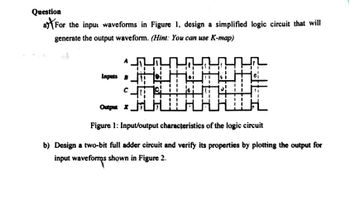
Transcribed Image Text:Question
a) (For the input waveforms in Figure 1, design a simplified logic circuit that will
generate the output waveform. (Hint: You can use K-map)
Inputs B
Output X
Figure 1: Input/output characteristics of the logic circuit
b) Design a two-bit full adder circuit and verify its properties by plotting the output for
input waveforms shown in Figure 2.

Transcribed Image Text:Question
(a) Design a circuit using D flip-flops that can be used to divide the clock frequency by
16.
(b) Draw the input and output waveforms for each stage to the circuit designed in part (a).
Expert Solution
This question has been solved!
Explore an expertly crafted, step-by-step solution for a thorough understanding of key concepts.
Step by stepSolved in 2 steps with 4 images

Knowledge Booster
Similar questions
- Q2/A) Design 8x1 multiplexer using 2x1 multiplexer? Q2 B)Simplify the Logic circuit shown below using K-map then draw the Simplified circuit? Q2/C) design logic block diagram for adding 12 to 5 using full adder showing the input for each adder?arrow_forwardH.W :- 1) A four logic-signal A,B,C,D are being used to represent a 4-bit binary number with A as the LSB and D as the MSB. The binary inputs are fed to a logic circuit that produces a logic 1 (HIGH) output only when the binary number is greater than 01102-610. Design this circuit. 2) repeat problem 1 for the output will be 0 (LOW) when the binary input is less than 01112-710- Saleem Lateefarrow_forwardBriefly explain the basic concepts of transistors and diodes can function as logic gates! Please Answer with explanation and full Step thank u.... I'm needed in 30-60 minutes...arrow_forward
- 2.31 For the timing diagram in Figure P2.3, synthesis the function f(x1, x2,x3) in the simplest sum-of-products form. X2 Time Figure P2.3 A timing diagram representing a logic functionarrow_forwardIn motor control of train, IGBT control AC motor save more energy than GTO due to less switching loss. State THREE more reasons why IGBT use in motor control has many advantages over GTO. If one of the freewheeling diode in your single phase inverter in above settings has reverse recovery failure. Describe what would happen to the circuit.arrow_forwardWhat is a TTL circuit? What are their main characteristics? (Input voltage and current, output voltage and current, Vcc, …)arrow_forward
- Y=f(A,B,C)=(0,4,5)+don't care(2)arrow_forwardConstruct the state diagram...arrow_forwardQ5 (a) Discuss, the major dıfferences between ticld programmable gatc arrays (FPGAS) and programmable logie devices (PLDS. where an FPGA may be approprate in a streamıng TV system. Simple multiplexers can be used to mimic a number of two-input logic functions by appropriate mapping of nputs X X, and SEL Show how the multiplexer shown in figure Q5a can be used to perform the function F= AOB (b) SEL Figure Q5a Figure Q5b (over) shows the schematic of a Xilinx 3000 sennes logic cell M Label the configuration bits of the various multiplexers n the celL with zeroed configuration bits selecting the topmost input to each multuplexer. Each multiplexer has -2 ns, the combinatorial loge block is guaranteed to have WS7 ns, and the D-type flip-flops have t4 ns and r 1 ns (c) We wish to construct a two-bit counter from this logie cell. where Q, and Q are the high and low order outputs of the counter, CLK is the clock signal, AR is an asynchronous reset signal, EN enables the counter, and LD allows…arrow_forward
- Implement the logic circuit in Figure 2 using only NAND gate A B C Xarrow_forward1. Design an Excess-3 (Ex-3) checker circuit for an input of 4-bits. (the output is logic 1 if the input is a valid Excess-3 and is 0 otherwise).arrow_forwardQ5. A general analysis of the switch-mode inverter shown in the figure below is to be done. The switching frequency f,, which is also the frequency of the triangular signal is 1450 Hz. The de voltage, Va, is 600 V. Output voltage is sinusoidal voltage with a frequency equal to 50 Hz. TA ADA. TA- ADA- VAN (Figure 8-4 on page 203 from Mohan's Book) a. Find the frequency modulation ratio, mr. b. Why the frequency modulation is chosen as an integer? c. Calculate the output voltage (rms value of first harmonic), when the amplitude modulation ratio, m., is equal to 0.8. d. Compute the rms values of the 5 most dominant harmonics of v4o at m,=0.8. e. Also indicate the frequencies at these harmonics you have found in part d appear.arrow_forward
arrow_back_ios
arrow_forward_ios
Recommended textbooks for you
 Introductory Circuit Analysis (13th Edition)Electrical EngineeringISBN:9780133923605Author:Robert L. BoylestadPublisher:PEARSON
 Delmar's Standard Textbook Of ElectricityElectrical EngineeringISBN:9781337900348Author:Stephen L. HermanPublisher:Cengage Learning
 Programmable Logic ControllersElectrical EngineeringISBN:9780073373843Author:Frank D. PetruzellaPublisher:McGraw-Hill Education
 Fundamentals of Electric CircuitsElectrical EngineeringISBN:9780078028229Author:Charles K Alexander, Matthew SadikuPublisher:McGraw-Hill Education
 Electric Circuits. (11th Edition)Electrical EngineeringISBN:9780134746968Author:James W. Nilsson, Susan RiedelPublisher:PEARSON
 Engineering ElectromagneticsElectrical EngineeringISBN:9780078028151Author:Hayt, William H. (william Hart), Jr, BUCK, John A.Publisher:Mcgraw-hill Education,

Introductory Circuit Analysis (13th Edition)
Electrical Engineering
ISBN:9780133923605
Author:Robert L. Boylestad
Publisher:PEARSON

Delmar's Standard Textbook Of Electricity
Electrical Engineering
ISBN:9781337900348
Author:Stephen L. Herman
Publisher:Cengage Learning

Programmable Logic Controllers
Electrical Engineering
ISBN:9780073373843
Author:Frank D. Petruzella
Publisher:McGraw-Hill Education

Fundamentals of Electric Circuits
Electrical Engineering
ISBN:9780078028229
Author:Charles K Alexander, Matthew Sadiku
Publisher:McGraw-Hill Education

Electric Circuits. (11th Edition)
Electrical Engineering
ISBN:9780134746968
Author:James W. Nilsson, Susan Riedel
Publisher:PEARSON

Engineering Electromagnetics
Electrical Engineering
ISBN:9780078028151
Author:Hayt, William H. (william Hart), Jr, BUCK, John A.
Publisher:Mcgraw-hill Education,