Introductory Circuit Analysis (13th Edition)
13th Edition
ISBN: 9780133923605
Author: Robert L. Boylestad
Publisher: PEARSON
expand_more
expand_more
format_list_bulleted
Question
Don't use ai to answer I will report you answer

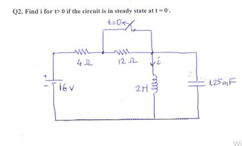
Transcribed Image Text:Q2. Find i for t> 0 if the circuit is in steady state at t = 0.
±=0</
ww
ww
42
122
Ji
+
·T.16v
1,25m F
2H
Wi
Expert Solution
This question has been solved!
Explore an expertly crafted, step-by-step solution for a thorough understanding of key concepts.
Step by stepSolved in 2 steps with 4 images

Knowledge Booster
Similar questions
- Hi im struggling to understand how you would sketch DC component Va and AC component va for the following questions. Could you show me how on both questions so i understand how to do it on different scenarios. thank you.Also is there like a universal formula i can use as every graph is not the same. Also can u show how to identify the period of each graph.arrow_forwardFor the circuit below with switch U1 closing at time t-0 and the initial current has reached steady state prior to t= 0, find the transient response voltage Vout and plot the results: R1 Vout U1 V1 15Vdo R3 C1 C2 20u 10u R2 1karrow_forwarda) What is the coupling constant between the two coils?b) Using the dot notation, determine if the induced voltages are additive or subtractive?c) Write the expressions for V1(t) and V2(t).d) Using KVL, determine the differential equation needed to solve for I2(t).e) Solve the differential equation in part d to get I2(t). Assume no energy stored in inductors at t=0.f) Use I1(t) and I2(t) to determine V1(t) and V2(t).arrow_forward
- Please show each and every step along the way. Thanks!arrow_forwardProblem 2 Define the initial current , the final current Is, the time constant r, and the current i at 32 us. 0mll 12v The switch is closed at t-0.arrow_forwardA thermometer is initially at a room temperature of 25°C. At a time t = 0, the thermometer is dipped in a boiling water bath having a temperature of 80°C. The thermometer is a first-order system with a time constant of 5.5 s. Plot the temperature reading versus time, showing in particular the 10-s reading. At what minimum time the thermometer will be within 10% of response from the steady-state value?arrow_forward
- Get a state space model for the following electrical system. Make sure to clearly define the states and input(s) using state space notation (x1,x2, ... , Xn for state variables, u1, U2, ... , Um for inputs, and so on). There are two outputs: the voltage of the capacitor C, and the current of the inductor L2. It is given that R1 = 5 N, R2 = 3 N, C = 10 F, L1 = 4 H, L2 = 7 H. %3D elll R2 R. Vsarrow_forwardLet be the first-order electric circuit shown in the figure below. It is known that the switch T changes state, from open to closed, at instant t=0 and that, once said switch is activated, the network reaches the stable state after 500 ms a) Find the expression for the voltage v(t), for all t>0b) Find the value of the capacitance Cc) Represent graphically, and approximately, the behavior as a function of time of the voltage found in part a)arrow_forwardPlease in typing format please ASAP for the Please I will like it please ASAP for thearrow_forward
- CURRENT IC( NEED NEAT HANDWRITTEN SOLUTION ONLY OTHERWISE DOWNVOTE).arrow_forward2. An aging battery generating 200e-5t volts is connected in series with a 20 ohm resistor, and a 0.01 farad capacitor. Assuming q = 0 at t = 0, find the charge and current for all t > 0. Show that the charge reaches a maximum and find the time it is reached. 3. In an arbitrary RC circuit with constant emf E, use the method of sepa- ration of variables to derive the formula Q(t) = Ae-t/RC + EC for the charge on the capacitor, where A is an arbitrary constant. If Q(0) = Qo, what is A? CS Scanned with CamScannerarrow_forwardHi Tutor please answer all step by step. please dont skip some parts.. Thank you. All continuous questionarrow_forward
arrow_back_ios
SEE MORE QUESTIONS
arrow_forward_ios
Recommended textbooks for you
 Introductory Circuit Analysis (13th Edition)Electrical EngineeringISBN:9780133923605Author:Robert L. BoylestadPublisher:PEARSON
 Delmar's Standard Textbook Of ElectricityElectrical EngineeringISBN:9781337900348Author:Stephen L. HermanPublisher:Cengage Learning
 Programmable Logic ControllersElectrical EngineeringISBN:9780073373843Author:Frank D. PetruzellaPublisher:McGraw-Hill Education
 Fundamentals of Electric CircuitsElectrical EngineeringISBN:9780078028229Author:Charles K Alexander, Matthew SadikuPublisher:McGraw-Hill Education
 Electric Circuits. (11th Edition)Electrical EngineeringISBN:9780134746968Author:James W. Nilsson, Susan RiedelPublisher:PEARSON
 Engineering ElectromagneticsElectrical EngineeringISBN:9780078028151Author:Hayt, William H. (william Hart), Jr, BUCK, John A.Publisher:Mcgraw-hill Education,

Introductory Circuit Analysis (13th Edition)
Electrical Engineering
ISBN:9780133923605
Author:Robert L. Boylestad
Publisher:PEARSON

Delmar's Standard Textbook Of Electricity
Electrical Engineering
ISBN:9781337900348
Author:Stephen L. Herman
Publisher:Cengage Learning

Programmable Logic Controllers
Electrical Engineering
ISBN:9780073373843
Author:Frank D. Petruzella
Publisher:McGraw-Hill Education

Fundamentals of Electric Circuits
Electrical Engineering
ISBN:9780078028229
Author:Charles K Alexander, Matthew Sadiku
Publisher:McGraw-Hill Education

Electric Circuits. (11th Edition)
Electrical Engineering
ISBN:9780134746968
Author:James W. Nilsson, Susan Riedel
Publisher:PEARSON

Engineering Electromagnetics
Electrical Engineering
ISBN:9780078028151
Author:Hayt, William H. (william Hart), Jr, BUCK, John A.
Publisher:Mcgraw-hill Education,