
Introductory Circuit Analysis (13th Edition)
13th Edition
ISBN: 9780133923605
Author: Robert L. Boylestad
Publisher: PEARSON
expand_more
expand_more
format_list_bulleted
Concept explainers
Videos
Textbook Question
thumb_up100%
Chapter 7, Problem 27P
For the ladder network in Fig. 7.90:
a. Find the current I.
b. Find the current I7.
c. Determine the voltages V3, V5 and V7
d. Calculate the power delivered to
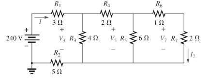
Fig. 7.90
Expert Solution & Answer
Want to see the full answer?
Check out a sample textbook solution
Students have asked these similar questions
3. For the network of Fig. 7.85 , determine:
a. VG.
b. ID and VGS.
c. VD and VS.
d. VDS.
O 20 V
2.2 kn
910 kQ
Dss = 10 mA
V, =-3.5 V
Vasa
110 kQ
1.1 ka
Calculate the total resistance of the voltage divider circuit shown in Fig. 7-1.
Rr
EDN
BAGLI
Calculate the input line current using the indicated input voltage.
MAdc
$1
0-100mAde
mA
R1
1K
R2
35Vdc
1K
B
R3
1.5K
RL
A
Fig. 7-1
Calculate the voltages across resistors R1, R2 and R3.
ERI
Vd
Er2
Era
Vd
Vdc
7U. A d'Arsonval voltmeter is shown below. Find the value of Rv for each of the following full Scale Readings:
a) 100 V
b)25 V
c) 500 mV
d) 5 mV
Rv
10 mV
.2 mA
Voltmeter
Chapter 7 Solutions
Introductory Circuit Analysis (13th Edition)
Ch. 7 - Which elements (individual elements, not...Ch. 7 - Repeat Problem 1 for the networks of Fig. 7.65....Ch. 7 - Determine RT for the networks in Fig. 7.66. Fig....Ch. 7 - Determine RT for the networks in Fig. 7.67. Fig....Ch. 7 - Find the total resistance for the configuration of...Ch. 7 - The total resistance RT for the network of Fig....Ch. 7 - For the network in Fig. 7.70. a. Does...Ch. 7 - For the network in Fig. 7.71: a. Determine RT. b....Ch. 7 - For the network of Fig. 7.72: a. find the currents...Ch. 7 - For the network of Fig. 7.73: Find the voltages V3...
Ch. 7 - For the network of Fig. 7.74 a. Find the voltages...Ch. 7 - For the circuit board in Fig. 7.75: Find the total...Ch. 7 - Find the value of each resistor for the network of...Ch. 7 - Find the resistance RT for the network of Fig....Ch. 7 - For the network in Fig. 7.78: a. Find currents...Ch. 7 - a. Find the magnitude and direction of the...Ch. 7 - Determine the currents I1andI2 for the network in...Ch. 7 - For the network in Fig. 7.81: a. Determine the...Ch. 7 - For the network in Fig. 7.82: a. Determine the...Ch. 7 - Determine the dc levels for the transistor network...Ch. 7 - For the network in Fig. 7.84: Determine the...Ch. 7 - For the network in Fig. 7.852 Determine RT by...Ch. 7 - For the network of Fig. 7.86: a. Find the voltages...Ch. 7 - For the network in Fig. 7.87: a. Determine the...Ch. 7 - For the network in Fig. 7.88 find the resistance...Ch. 7 - If all the resistors of the cube in Fig. 7.89 are...Ch. 7 - For the ladder network in Fig. 7.90: a. Find the...Ch. 7 - For the ladder network in Fig. 7.91: a. Determine...Ch. 7 - Given the voltage divider supply in Fig. 7.92: a....Ch. 7 - Determine the voltage divider supply resistors for...Ch. 7 - A studio lamp requires 40 V at 50 mA to burn...Ch. 7 - For the system in Fig. 7.94 a. At first exposure,...Ch. 7 - For the potentiometer in Fig. 7.95: a. What are...Ch. 7 - Prob. 34PCh. 7 - Given the voltmeter reading V = 27 V in Fig. 7.97...Ch. 7 - Determine the power delivered to the 6 load in...Ch. 7 - For the multiple ladder configuration in Fig....Ch. 7 - An iron-vane movement is rated 1 mA, 100 . a. What...Ch. 7 - Using a 50 A, 1000 movement, design a multirange...Ch. 7 - An iron-vane movement is rated 50 A , 1000 a....Ch. 7 - Using a 1 mA, 1000 movement, design a multirange...Ch. 7 - A digital meter has an internal resistance of 10 M...Ch. 7 - a. Design a series ohmmeter using a 100 A, 1000...Ch. 7 - Prob. 44PCh. 7 - Determine the reading of the ohmmeter for each...Ch. 7 - Using PSpice or Multisim, verify the result of...Ch. 7 - Using PSpice or Multisim, Confirm the solutions of...Ch. 7 - Using PSpice or Multisim, verify the result of...Ch. 7 - Using PSpice or Multisim, find voltage V6 of Fig....Ch. 7 - Using PSpice or Multisim, find voltages Vb and Vc...
Additional Engineering Textbook Solutions
Find more solutions based on key concepts
Find I0 and I1 in the circuit in Fig.P2.12.
Basic Engineering Circuit Analysis
For the “tank” circuit in Fig. 14.79, find the resonant frequency.
Figure 14.79
For Probs. 14.39, 14.71, and 1...
Fundamentals of Electric Circuits
Three point charges of equal magnitude q, that will yield a zero net electric field at the origin.
Engineering Electromagnetics
Does the severity of an electric shock increase ordecrease with eh of the following changes? a. A decrease in t...
Electric Motors and Control Systems
Assume a telephone signal travels through a cable at two-thirds the speed of light. How long does it take the s...
Electric Circuits (10th Edition)
What is the color code for a 365- five-band precision resistor with a tolerance of 5 percent?
ELECTRICITY FOR TRADES (LOOSELEAF)
Knowledge Booster


Learn more about
Need a deep-dive on the concept behind this application? Look no further. Learn more about this topic, electrical-engineering and related others by exploring similar questions and additional content below.Similar questions
- For photovoltaic (PV) systems the shading of the panels should be avoided, because: a. The production of the shaded panel and the panels connected parallel to it decreases significantly. b. The production (power output) of the shaded panel and the panels connected in series to it decreases significantly. c. The whole PV system’s production decreases significantly, regardless of the shaded panel position. d. The shaded panel’s production decreases significantlyarrow_forward4. Find the total equivalent Resistance (Rab). 652 212 12 barrow_forward4. Find the total equivalent Resistance (Rab). 612 22 30 952 52arrow_forward
- Design and draw a series and parallel combination circuit comprising of oneseries resistor and two parallel branches, each having one resistor andrespective branch currents of: 1/3 mA and 2/3 mA, using a DC power supplyof 3V.arrow_forwardProblem No. 7 *13. Determine V, and In for the network of Fig. 163. 2 k. Si +10 Vo GaAs 2 k2 2 ka FIG. 163arrow_forwardEXAMPLE 14 For the parallel network in Fig. 6 a. Without making a single calculation, make a guess on the total resistance. b. Calculate the total resistance and compare it to your guess in part (a). c. Without making a single calculation, which branch will have the most current? Which will have the least? d. Calculate the current through each branch, and compare your results to the assumptions of part (c). e. Find the source current and test whether it equals the sum of the branch currents. f. How does the magnitude of the source current compare to that of the branch currents? RT 10 kn R 22 kn R, 1.2 kn R 56 kflarrow_forward
- Find currents for each loop using Mesh analysis 7.50 RA E 3 V R1 9.1 kM 6.8 kf 2.2 kf2 R33 kN 3.3 18 Varrow_forward7. A workshop 100 m x 50 m is to be illuminated with intensity of illumination being 50 lux. Determine (a) the number of lamps required and (b) design a suitable scheme of lighting if coefficient of utilization = 0.9; maintenance factor = 0.7 and efficiency of lamps = 80 lm/W. Use 100-W lamps. [50 lamps]arrow_forwardThere are five electric appliances, viz. electric heater, electric lamp, an electric fan,computer and an exhaust fan are connected in parallel in a household. Ther resistanceelectric appliances are 409,522, 80, 200 and 100 respectively. If ane electriccurrent of 240V is flowing through the circuit then find following 1. Evaluate the electric current through heater 2. Determine electric current through electric lamp 3. Find out total resistance of the circuit 4.calculate electric current through circuit 5.evaluate electric current through electric fanarrow_forward
- Mesh Analysis Q.1) Determine the value of the current I for the network. 4.7 kf2 ,1.1 k. BV. 6.8 kN 6.8 kN 6.8 kl Q.2) Determine the value of the current source Is for the network below. R, 1 kN R 2 kN R$2 kN R5 2 kN 2 ΚΩ R E 10 V R 2 kNarrow_forwarda.) Both voltage sources are at 1 V. What is the voltage (in V) at node 1? will give thumbs up!!arrow_forwardB) You are required to analyze the operation of DC circuit shown in Fig.2 and apply Ohm's law and Kirchhoff's voltage and current laws to find all the Voltages (with the associated polarities) and currents (with the associated direction)for all resistors. Test your procedures by simulate the circuit using Multisim to verify your hand calculations (Show all steps, equations, and calculations). IR1 R1 IR6 5.1KO IR3 R6 1ko IR2 ww 2.2KO R3 ww R2 1KO V2 V1 10V 5V IR5 IR7 IR4 1KO 2.2KΩ R7 1kQ R4 R5 Figure 2: DC-Circuit ww wwarrow_forward
arrow_back_ios
SEE MORE QUESTIONS
arrow_forward_ios
Recommended textbooks for you
 Delmar's Standard Textbook Of ElectricityElectrical EngineeringISBN:9781337900348Author:Stephen L. HermanPublisher:Cengage Learning
Delmar's Standard Textbook Of Electricity
Electrical Engineering
ISBN:9781337900348
Author:Stephen L. Herman
Publisher:Cengage Learning
Current Divider Rule; Author: Neso Academy;https://www.youtube.com/watch?v=hRU1mKWUehY;License: Standard YouTube License, CC-BY