
Microelectronics: Circuit Analysis and Design
4th Edition
ISBN: 9780073380643
Author: Donald A. Neamen
Publisher: McGraw-Hill Companies, The
expand_more
expand_more
format_list_bulleted
Videos
Textbook Question
Chapter 7, Problem 7.71P
Repeat Problem 7.70 for the common−base circuit in Figure P7.71. Assume
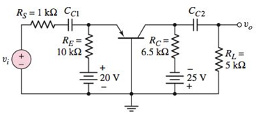
Figure P7.71
Expert Solution & Answer
Want to see the full answer?
Check out a sample textbook solution
Students have asked these similar questions
Use Figure 7.1. What is the current gain of a
2N3904 when the collector current is 100 mA and the junction temperature is equal to 125°C?
7. Although, geometrically no difference exists between the source and a drain of a
MOSFET, drain and source terminals of a MOSFET are distinguished electrically.
How are they distinguished in an nMOS transistor?
Bipolar junction transistors (BJTs) are considered “normally-off” devices, because their natural state with no signal applied to the base is no ........... between emitter and collector, like an open switch. * Your answer All field-effect transistors are unipolar rather than bipolar devices. That is, the main current through them is comprised either of ........... through an N-type semiconductor *
Chapter 7 Solutions
Microelectronics: Circuit Analysis and Design
Ch. 7 - (a) For the circuit shown in Figure 7.2, the...Ch. 7 - The circuit shown in Figure 7.10 has parameters of...Ch. 7 - For the equivalent circuit shown in Figure 7.13,...Ch. 7 - The equivalent circuit in Figure 7.14 has circuit...Ch. 7 - The parameters in the circuit shown in Figure 7.15...Ch. 7 - For the circuit shown in Figure 7.2 1(a), the...Ch. 7 - Consider the circuit shown in Figure 7.22(a). The...Ch. 7 - For the emitterfollower circuit shown in Figure...Ch. 7 - The circuit shown in Figure 7.27(a) has parameters...Ch. 7 - Consider the common-base circuit shown in Figure...
Ch. 7 - The commonemitter circuit shown in Figure 7.34...Ch. 7 - A bipolar transistor has parameters o=120 ,...Ch. 7 - Prob. 7.9EPCh. 7 - For the circuit in Figure 7.41(a), the parameters...Ch. 7 - A bipolar transistor is biased at ICQ=120A and its...Ch. 7 - For the transistor described in Example 7.9 and...Ch. 7 - The parameters of a bipolar transistor are: o=150...Ch. 7 - The parameters of an nchannel MOSFET are...Ch. 7 - For the circuit in Figure 7.55, the transistor...Ch. 7 - An nchannel MOSFET has parameters Kn=0.4mA/V2 ,...Ch. 7 - An nchannel MOSFET has a unitygain bandwidth of...Ch. 7 - For a MOSFET, assume that gm=1.2mA/V . The basic...Ch. 7 - The transistor in the circuit in Figure 7.60 has...Ch. 7 - Consider the commonbase circuit in Figure 7.64....Ch. 7 - The cascode circuit in Figure 7.65 has parameters...Ch. 7 - Prob. 7.12TYUCh. 7 - For the circuit in Figure 7.72, the transistor...Ch. 7 - Describe the general frequency response of an...Ch. 7 - Describe the general characteristics of the...Ch. 7 - Describe what is meant by a system transfer...Ch. 7 - What is the criterion that defines a corner, or...Ch. 7 - Describe what is meant by the phase of the...Ch. 7 - Describe the time constant technique for...Ch. 7 - Describe the general frequency response of a...Ch. 7 - Sketch the expanded hybrid model of the BJT.Ch. 7 - Prob. 9RQCh. 7 - Prob. 10RQCh. 7 - Prob. 11RQCh. 7 - Sketch the expanded smallsignal equivalent circuit...Ch. 7 - Define the cutoff frequency for a MOSFET.Ch. 7 - Prob. 14RQCh. 7 - Why is there not a Miller effect in a commonbase...Ch. 7 - Describe the configuration of a cascode amplifier.Ch. 7 - Why is the bandwidth of a cascode amplifier...Ch. 7 - Why is the bandwidth of the emitterfollower...Ch. 7 - Prob. 7.1PCh. 7 - Prob. 7.2PCh. 7 - Consider the circuit in Figure P7.3. (a) Derive...Ch. 7 - Consider the circuit in Figure P7.4 with a signal...Ch. 7 - Consider the circuit shown in Figure P7.5. (a)...Ch. 7 - A voltage transfer function is given by...Ch. 7 - Sketch the Bode magnitude plots for the following...Ch. 7 - (a) Determine the transfer function corresponding...Ch. 7 - Consider the circuit shown in Figure 7.15 with...Ch. 7 - For the circuit shown in Figure P7.12, the...Ch. 7 - The circuit shown in Figure 7.10 has parameters...Ch. 7 - The transistor shown in Figure P7.14 has...Ch. 7 - Consider the circuit shown in Figure P7.15. The...Ch. 7 - The transistor in the circuit shown in Figure...Ch. 7 - For the common-emitter circuit in Figure P7.17,...Ch. 7 - The transistor in the circuit in Figure P7.20 has...Ch. 7 - For the circuit in Figure P7.21, the transistor...Ch. 7 - (a) For the circuit shown in Figure P7.22, write...Ch. 7 - Consider the circuit shown in Figure P7.23. (a)...Ch. 7 - The parameters of the transistor in the circuit in...Ch. 7 - A capacitor is placed in parallel with RL in the...Ch. 7 - The parameters of the transistor in the circuit in...Ch. 7 - Prob. D7.27PCh. 7 - The circuit in Figure P7.28 is a simple output...Ch. 7 - Reconsider the circuit in Figure P728. The...Ch. 7 - Consider the circuit shown in Figure P7.32. The...Ch. 7 - The commonemitter circuit in Figure P7.35 has an...Ch. 7 - Consider the commonbase circuit in Figure 7.33 in...Ch. 7 - Prob. 7.39PCh. 7 - The parameters of the transistor in the circuit in...Ch. 7 - In the commonsource amplifier in Figure 7.25(a) in...Ch. 7 - A bipolar transistor has fT=4GHz , o=120 , and...Ch. 7 - A highfrequency bipolar transistor is biased at...Ch. 7 - (a) The frequency fT of a bipolar transistor is...Ch. 7 - The circuit in Figure P7.48 is a hybrid ...Ch. 7 - Consider the circuit in Figure P7.49. Calculate...Ch. 7 - A common-emitter equivalent circuit is shown in...Ch. 7 - For the common-emitter circuit in Figure 7.41(a)...Ch. 7 - For the commonemitter circuit in Figure P7.52,...Ch. 7 - Consider the circuit in Figure P7.52. The resistor...Ch. 7 - The parameters of the circuit shown in Figure...Ch. 7 - The parameters of an nchannel MOSFET are kn=80A/V2...Ch. 7 - Find fT for a MOSFET biased at IDQ=120A and...Ch. 7 - Fill in the missing parameter values in the...Ch. 7 - (a) An nchannel MOSFET has an electron mobility of...Ch. 7 - A commonsource equivalent circuit is shown in...Ch. 7 - Prob. 7.60PCh. 7 - The parameters of an ideal nchannel MOSFET are...Ch. 7 - Figure P7.62 shows the highfrequency equivalent...Ch. 7 - For the FET circuit in Figure P7.63, the...Ch. 7 - The midband voltage gain of a commonsource MOSFET...Ch. 7 - Prob. 7.65PCh. 7 - Prob. 7.67PCh. 7 - The bias voltages of the circuit shown in Figure...Ch. 7 - For the PMOS commonsource circuit shown in Figure...Ch. 7 - In the commonbase circuit shown in Figure P7.70,...Ch. 7 - Repeat Problem 7.70 for the commonbase circuit in...Ch. 7 - In the commongate circuit in Figure P7.72, the...
Knowledge Booster


Learn more about
Need a deep-dive on the concept behind this application? Look no further. Learn more about this topic, electrical-engineering and related others by exploring similar questions and additional content below.Similar questions
- Describe the basic principle of operation of a bipolar junction transistor. Include explanation for the following : When minority carriers flow across the transistor Why the collector current is almost unaffected by the collector potentialarrow_forwardAll field-effect transistors are unipolar rather than bipolar devices. That is, the main current through them is comprised either of through an N-type semiconductor * ..... .....arrow_forwardWith Neat sketch explain the construction, operation, VI characteristics, application and features of the power semiconductor device which is having low on state loss and small switching frequency operationarrow_forward
- This is about Bipolar Junction Transistors: Discuss collector characteristic curves and identify and explain the different regions.arrow_forwardDescribe the basic principle of operation of a bipolar junction transistor. Includeexplanation for the following:i. When minority carriers flow across the transistorii. why the collector current is almost unaffected by the collector potentialarrow_forwardWith Neat sketch explain the construction, operation, VI characteristics, application and features of the power semiconductor device which is having low on state loss and high switching frequency operation.arrow_forward
- A two-junction semiconductor transistor with a positive type collector and emitter, and negative type base is known as?arrow_forward4. The band gap between conduction and valance band in an insulator is (Low Very low High Moderate) 5. Operating point of a transistor must be independent of (Biasing Amplification Variations in parameters Filtration) 6. When a transistor operating at the central of the load line is declining, the current gain will change the Q-point (down up nowhere of the load line) 7. A bipolar junction transistor when used as a switch, operates in (cut-off and active region active and saturation region cut-off and saturation region all of these) 8. Inversion layer in an MOS circuit is made by (doping impact ionization tunnelling electric field) 9. What are the applications of semiconductor devices? (Microprocessors Analog eircuits High voltage applications All of these)arrow_forwardGive a conclusion about BIPOLAR JUNCTION TRANSISTOR: OPERATION AND ITS CHARACTERISTIC CURVEarrow_forward
- with the aid of a diagram describe a simple common emitter circuit with npn bipolar transitor and discus the relationship between base emitter voltage and base currentarrow_forwardConsider the common-base BJT amplifier in Figure 7. Assume that the following valuesremain constant during the operating conditions, B AC= 110 and VBE = 0.5V, Draw the ac equivalent circuit for the BJT amplifier circuit, and calculate the following ac values for the amplifier:i. R outii. R in(emitter) iii. Av iv. Ai v. Aparrow_forward5- a-) Define the MOSFET in the figure, explain by drawing its input and output circuit characteristics.b-) Since k=0.1 mA/V2, VGS=5V and VT=2.5V for this MOSFET, find the VDS voltage using the circuit.arrow_forward
arrow_back_ios
SEE MORE QUESTIONS
arrow_forward_ios
Recommended textbooks for you
 Introductory Circuit Analysis (13th Edition)Electrical EngineeringISBN:9780133923605Author:Robert L. BoylestadPublisher:PEARSON
 Delmar's Standard Textbook Of ElectricityElectrical EngineeringISBN:9781337900348Author:Stephen L. HermanPublisher:Cengage Learning
 Programmable Logic ControllersElectrical EngineeringISBN:9780073373843Author:Frank D. PetruzellaPublisher:McGraw-Hill Education
 Fundamentals of Electric CircuitsElectrical EngineeringISBN:9780078028229Author:Charles K Alexander, Matthew SadikuPublisher:McGraw-Hill Education
 Electric Circuits. (11th Edition)Electrical EngineeringISBN:9780134746968Author:James W. Nilsson, Susan RiedelPublisher:PEARSON
 Engineering ElectromagneticsElectrical EngineeringISBN:9780078028151Author:Hayt, William H. (william Hart), Jr, BUCK, John A.Publisher:Mcgraw-hill Education,
Introductory Circuit Analysis (13th Edition)
Electrical Engineering
ISBN:9780133923605
Author:Robert L. Boylestad
Publisher:PEARSON
Delmar's Standard Textbook Of Electricity
Electrical Engineering
ISBN:9781337900348
Author:Stephen L. Herman
Publisher:Cengage Learning
Programmable Logic Controllers
Electrical Engineering
ISBN:9780073373843
Author:Frank D. Petruzella
Publisher:McGraw-Hill Education
Fundamentals of Electric Circuits
Electrical Engineering
ISBN:9780078028229
Author:Charles K Alexander, Matthew Sadiku
Publisher:McGraw-Hill Education
Electric Circuits. (11th Edition)
Electrical Engineering
ISBN:9780134746968
Author:James W. Nilsson, Susan Riedel
Publisher:PEARSON
Engineering Electromagnetics
Electrical Engineering
ISBN:9780078028151
Author:Hayt, William H. (william Hart), Jr, BUCK, John A.
Publisher:Mcgraw-hill Education,
Diode Logic Gates - OR, NOR, AND, & NAND; Author: The Organic Chemistry Tutor;https://www.youtube.com/watch?v=9lqwSaIDm2g;License: Standard Youtube License