
Microelectronics: Circuit Analysis and Design
4th Edition
ISBN: 9780073380643
Author: Donald A. Neamen
Publisher: McGraw-Hill Companies, The
expand_more
expand_more
format_list_bulleted
Videos
Textbook Question
Chapter 7, Problem 7.28P
The circuit in Figure P7.28 is a simple output stage of an audio amplifier.The transistor parameters are
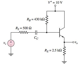
Figure P7.28
Expert Solution & Answer
Want to see the full answer?
Check out a sample textbook solution
Students have asked these similar questions
7
Name the circuit shown below?
Please justify the name with brief explanation of the working of this circuit.
Page 3 of 6
Final Assignment
If the input signal is a high frequency input signal to an AM receiver (very less amplitude) will this serve
the purpose. If Yes Justify? If NO Justify and give the modification which will make it suitable for the
above mentioned purpose.
out
RL
What is the condition for over modulation and what are its effects?
9.
For the circuit shown in Figure Bl19a,
Ve- 20V
Rc 3k
R = 10k 2
Wr
VCE
VBB=3V
Figure B19a
i)
Sketch the DC load line in the Graph B19.
ii) Calculate the Q point, if the zero signal base current is 50 µA and a -0.991. Mark the
Q point in load line.
D Focus
重
f8
fg
f10
insort sc
f12
&
近
Chapter 7 Solutions
Microelectronics: Circuit Analysis and Design
Ch. 7 - (a) For the circuit shown in Figure 7.2, the...Ch. 7 - The circuit shown in Figure 7.10 has parameters of...Ch. 7 - For the equivalent circuit shown in Figure 7.13,...Ch. 7 - The equivalent circuit in Figure 7.14 has circuit...Ch. 7 - The parameters in the circuit shown in Figure 7.15...Ch. 7 - For the circuit shown in Figure 7.2 1(a), the...Ch. 7 - Consider the circuit shown in Figure 7.22(a). The...Ch. 7 - For the emitterfollower circuit shown in Figure...Ch. 7 - The circuit shown in Figure 7.27(a) has parameters...Ch. 7 - Consider the common-base circuit shown in Figure...
Ch. 7 - The commonemitter circuit shown in Figure 7.34...Ch. 7 - A bipolar transistor has parameters o=120 ,...Ch. 7 - Prob. 7.9EPCh. 7 - For the circuit in Figure 7.41(a), the parameters...Ch. 7 - A bipolar transistor is biased at ICQ=120A and its...Ch. 7 - For the transistor described in Example 7.9 and...Ch. 7 - The parameters of a bipolar transistor are: o=150...Ch. 7 - The parameters of an nchannel MOSFET are...Ch. 7 - For the circuit in Figure 7.55, the transistor...Ch. 7 - An nchannel MOSFET has parameters Kn=0.4mA/V2 ,...Ch. 7 - An nchannel MOSFET has a unitygain bandwidth of...Ch. 7 - For a MOSFET, assume that gm=1.2mA/V . The basic...Ch. 7 - The transistor in the circuit in Figure 7.60 has...Ch. 7 - Consider the commonbase circuit in Figure 7.64....Ch. 7 - The cascode circuit in Figure 7.65 has parameters...Ch. 7 - Prob. 7.12TYUCh. 7 - For the circuit in Figure 7.72, the transistor...Ch. 7 - Describe the general frequency response of an...Ch. 7 - Describe the general characteristics of the...Ch. 7 - Describe what is meant by a system transfer...Ch. 7 - What is the criterion that defines a corner, or...Ch. 7 - Describe what is meant by the phase of the...Ch. 7 - Describe the time constant technique for...Ch. 7 - Describe the general frequency response of a...Ch. 7 - Sketch the expanded hybrid model of the BJT.Ch. 7 - Prob. 9RQCh. 7 - Prob. 10RQCh. 7 - Prob. 11RQCh. 7 - Sketch the expanded smallsignal equivalent circuit...Ch. 7 - Define the cutoff frequency for a MOSFET.Ch. 7 - Prob. 14RQCh. 7 - Why is there not a Miller effect in a commonbase...Ch. 7 - Describe the configuration of a cascode amplifier.Ch. 7 - Why is the bandwidth of a cascode amplifier...Ch. 7 - Why is the bandwidth of the emitterfollower...Ch. 7 - Prob. 7.1PCh. 7 - Prob. 7.2PCh. 7 - Consider the circuit in Figure P7.3. (a) Derive...Ch. 7 - Consider the circuit in Figure P7.4 with a signal...Ch. 7 - Consider the circuit shown in Figure P7.5. (a)...Ch. 7 - A voltage transfer function is given by...Ch. 7 - Sketch the Bode magnitude plots for the following...Ch. 7 - (a) Determine the transfer function corresponding...Ch. 7 - Consider the circuit shown in Figure 7.15 with...Ch. 7 - For the circuit shown in Figure P7.12, the...Ch. 7 - The circuit shown in Figure 7.10 has parameters...Ch. 7 - The transistor shown in Figure P7.14 has...Ch. 7 - Consider the circuit shown in Figure P7.15. The...Ch. 7 - The transistor in the circuit shown in Figure...Ch. 7 - For the common-emitter circuit in Figure P7.17,...Ch. 7 - The transistor in the circuit in Figure P7.20 has...Ch. 7 - For the circuit in Figure P7.21, the transistor...Ch. 7 - (a) For the circuit shown in Figure P7.22, write...Ch. 7 - Consider the circuit shown in Figure P7.23. (a)...Ch. 7 - The parameters of the transistor in the circuit in...Ch. 7 - A capacitor is placed in parallel with RL in the...Ch. 7 - The parameters of the transistor in the circuit in...Ch. 7 - Prob. D7.27PCh. 7 - The circuit in Figure P7.28 is a simple output...Ch. 7 - Reconsider the circuit in Figure P728. The...Ch. 7 - Consider the circuit shown in Figure P7.32. The...Ch. 7 - The commonemitter circuit in Figure P7.35 has an...Ch. 7 - Consider the commonbase circuit in Figure 7.33 in...Ch. 7 - Prob. 7.39PCh. 7 - The parameters of the transistor in the circuit in...Ch. 7 - In the commonsource amplifier in Figure 7.25(a) in...Ch. 7 - A bipolar transistor has fT=4GHz , o=120 , and...Ch. 7 - A highfrequency bipolar transistor is biased at...Ch. 7 - (a) The frequency fT of a bipolar transistor is...Ch. 7 - The circuit in Figure P7.48 is a hybrid ...Ch. 7 - Consider the circuit in Figure P7.49. Calculate...Ch. 7 - A common-emitter equivalent circuit is shown in...Ch. 7 - For the common-emitter circuit in Figure 7.41(a)...Ch. 7 - For the commonemitter circuit in Figure P7.52,...Ch. 7 - Consider the circuit in Figure P7.52. The resistor...Ch. 7 - The parameters of the circuit shown in Figure...Ch. 7 - The parameters of an nchannel MOSFET are kn=80A/V2...Ch. 7 - Find fT for a MOSFET biased at IDQ=120A and...Ch. 7 - Fill in the missing parameter values in the...Ch. 7 - (a) An nchannel MOSFET has an electron mobility of...Ch. 7 - A commonsource equivalent circuit is shown in...Ch. 7 - Prob. 7.60PCh. 7 - The parameters of an ideal nchannel MOSFET are...Ch. 7 - Figure P7.62 shows the highfrequency equivalent...Ch. 7 - For the FET circuit in Figure P7.63, the...Ch. 7 - The midband voltage gain of a commonsource MOSFET...Ch. 7 - Prob. 7.65PCh. 7 - Prob. 7.67PCh. 7 - The bias voltages of the circuit shown in Figure...Ch. 7 - For the PMOS commonsource circuit shown in Figure...Ch. 7 - In the commonbase circuit shown in Figure P7.70,...Ch. 7 - Repeat Problem 7.70 for the commonbase circuit in...Ch. 7 - In the commongate circuit in Figure P7.72, the...
Knowledge Booster


Learn more about
Need a deep-dive on the concept behind this application? Look no further. Learn more about this topic, electrical-engineering and related others by exploring similar questions and additional content below.Similar questions
- Find the resonance point and the half-width of the speed versus frequency curve for the damped harmonic oscillator, under the action of a sinusoidal driving force. *It is all the dataarrow_forwardQ7. Find the relationship between the output and the input (Vout/Vin ) in the amplifier circuit depicted in Figure Q7 (a) and (b). State any assumptions you make. Please step by step I need to understand.arrow_forwardA channel having a bandwidth of 1 kHz, the power of signal is 10 W and the power of noise is 5 W. Determine the channel capacity. Or: A channel having a bandwidth of 1 kHz and Signal to Noise Ratio (SNR) is 2. Determine the channel capacity.arrow_forward
- This problem is AC analysis problem. DC analysis is not needed to answer the question. A) If we assume that the peak voltage of Vbe must be less than 10 mV to avoid small signal violations determine the value of Rsig if Vi has a peak amplitude of 1 V and Is = 1mA. Hint: Don't forget r!! Answer: Rsig =. B) If you did the DC analysis on this problem and calculated Vc = 50 mV and Vs = -100 mV what is the maximum amplitude of the output voltage while the circuit stays in active mode. Answer: Vo,max =, When you "verify" a mode of operation you will need to calculate all three voltages (Vc, Ve, VE for BJTS and VG, Vs, Vp for MOSFETS) and show the correct two conditions are satisfied. Assume Capacitors acts like open circuits at DC and short circuits for AC. > Assume the following: 5V o Beta = 100 O VBE = 0.7 o V: (Thermal) = 26 mV o Vr (Threshold) = 2V O VA = - o For MOSFET saturation mode: assume: lp = K(VGs-Vr)? (Assume K = 10 mA/V²). 5kn C2 01 C1 Rsig 1kn 10k Vi IIs :C3 1mA -5Varrow_forwardWrite the expression for the output voltage of a balanced modulatorarrow_forward7.26. The sampling theorem, as we have derived it, states that a signal x(1) must be sam- pled at a rate greater than its bandwidth (or equivalently, a rate greater than twice its highest frequency). This implies that if x(1) has a spectrum as indicated in Figure P7.26(a) then x(1) must be sampled at a rate greater than 2002. However, since the signal has most of its energy concentrated in a narrow band, it would seem reason- able to expect that a sampling rate lower than twice the highest frequency could be used. A signal whose energy is concentrated in a frequency band is often referred to as a bandpass signal. There are a variety of techniques for sampling such signals, generally referred to as bandpass-sampling techniques. x(t) X(jw) MA @₁ W₂ (a) -W₂ -W₁ p(t) = Σ 8(t-nT) Io. Xp (t) H(jw) 1 -Wo n Wa p(t) H(jw) A+ (b) 3° W wp w x, (t) Figure P7.26arrow_forward
- 12- A DVM measure... a- peak value. b- RMS value. Average value. d- peak to peak value. 13 The study of energy distribution across the frequency spectrum of a given electrical signal is done by a Distortion meter b-wave analyzer.arrow_forward7.03. Find the type of the feedback in the given circuit. cc RB Ze Cc RE Cc (A) Current series (B) Voltage shunt (C) Voltage series. (D) Current shuntarrow_forwardA) what name the modulation scheme in the blue curve in A and C B) what is the duty cycle in B C) What is the sampling Frequency in B D) write and equation that represent the modulated signal in B solve all parts or will dislikearrow_forward
- b) Draw the block diagram of the phase - locked loop (PLL) that can be used to demodulate FM signals. Explain briefly . the operation of this demodulatorarrow_forwardDraw the AC equivalent circuit and find Zi, Zo, Av, Ai (ignore the effect of To). Show all the necessary derivations and label all the parameters properly.arrow_forwardWhich statement is true? a. In FSK, the modulating signal and the carrier signal are both analog b. In FSK, the modulating signal and the modulated signala re both digital c. In FSK, the modulating signal and the modulated signal are both analog d. In FSK, the carrier signal is analog and the modulating signal is digitalarrow_forward
arrow_back_ios
SEE MORE QUESTIONS
arrow_forward_ios
Recommended textbooks for you
 Introductory Circuit Analysis (13th Edition)Electrical EngineeringISBN:9780133923605Author:Robert L. BoylestadPublisher:PEARSON
 Delmar's Standard Textbook Of ElectricityElectrical EngineeringISBN:9781337900348Author:Stephen L. HermanPublisher:Cengage Learning
 Programmable Logic ControllersElectrical EngineeringISBN:9780073373843Author:Frank D. PetruzellaPublisher:McGraw-Hill Education
 Fundamentals of Electric CircuitsElectrical EngineeringISBN:9780078028229Author:Charles K Alexander, Matthew SadikuPublisher:McGraw-Hill Education
 Electric Circuits. (11th Edition)Electrical EngineeringISBN:9780134746968Author:James W. Nilsson, Susan RiedelPublisher:PEARSON
 Engineering ElectromagneticsElectrical EngineeringISBN:9780078028151Author:Hayt, William H. (william Hart), Jr, BUCK, John A.Publisher:Mcgraw-hill Education,
Introductory Circuit Analysis (13th Edition)
Electrical Engineering
ISBN:9780133923605
Author:Robert L. Boylestad
Publisher:PEARSON
Delmar's Standard Textbook Of Electricity
Electrical Engineering
ISBN:9781337900348
Author:Stephen L. Herman
Publisher:Cengage Learning
Programmable Logic Controllers
Electrical Engineering
ISBN:9780073373843
Author:Frank D. Petruzella
Publisher:McGraw-Hill Education
Fundamentals of Electric Circuits
Electrical Engineering
ISBN:9780078028229
Author:Charles K Alexander, Matthew Sadiku
Publisher:McGraw-Hill Education
Electric Circuits. (11th Edition)
Electrical Engineering
ISBN:9780134746968
Author:James W. Nilsson, Susan Riedel
Publisher:PEARSON
Engineering Electromagnetics
Electrical Engineering
ISBN:9780078028151
Author:Hayt, William H. (william Hart), Jr, BUCK, John A.
Publisher:Mcgraw-hill Education,
Diode Logic Gates - OR, NOR, AND, & NAND; Author: The Organic Chemistry Tutor;https://www.youtube.com/watch?v=9lqwSaIDm2g;License: Standard Youtube License