
Videos
Consider the circuit shown in Figure P7.5. (a) What is the value of the voltage transfer function
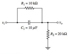
Figure P7.5
Want to see the full answer?
Check out a sample textbook solution
Chapter 7 Solutions
Microelectronics: Circuit Analysis and Design


- Answer the following questions: a)" 1 Given the output voltage signal Vo(s) below, find the output voltage in the time domain vo(t). 2 Vo(s)= (s+2)(s+8) b) Discuss the application of Ohm's Law for a given R and C in series in both time and frequency domains. Files You can drag and drop files here to add them. Next pagearrow_forwardA sinusoid signal v(n) = 5 sin( @₂ .n) with f=5 Hz and fs = 10 kHz has to be quantized @ (Vq(n) = Q[v(n)]) with a midtreat quantizer. The range of the signal is ±5 V and the word length of the quantizer 4 bits. The quantizer is at digital full scale. (a) How many quantization levels L does the quantizer have? What is the value of A? (b) Sketch the input-output characteristic of the quantizer. How different is a midtreat quantizer to a midrise quantizer. (c) For time index n = 1250 calculate the quantized value v₁ (n), the quantization error eq(n) and represent vą (n) using RZ code. (d) Calculate the power P of the quantization noise. (e) Determine the SNR in dB.arrow_forwardTime-domain analysis of a resonant circuit Figure 1 shows a resonant circuit where all components can be considered ideal, V is a de voltage source, I is a de current source. At 1 = 0, v(0) = Vo, i(0) = I,. Figure 1 a) Solve differential equations describing the circuit to find analytical expressions for v(t) and i(t). What is the period of the waveforms? b) Find an expression for the maximum value of v. c) Find an expression for the maximum value of i. d) Find an expression for the value of v at the time when i is at its maximum. e) Find and expression for the value of i at the time when v is at its maximum.arrow_forward
- "Time domain representation is an ac signal representation considers the time-varying nature of the signal, specifically its sinusoidal form." O True O Falsearrow_forwardFind the transient current (a general solution) in the RLC-circuit in the figure below for the given data. R = 6 N, L = 0.2 H, C = 0.025 F, E = 190 sin (10t) V R E(t) = E, sinot Write arbitrary constants as C1 and C2. llarrow_forward) Using the properties of F.T., Calculate the F.T. of the signal sin(3nt) sin (5nt) x(t) = 5 %3D t2arrow_forward
- Draw the waveform of the following signal (draw from n=0 to n=5 only): X(n)=3u(n)-2r(n-2)+4r(n-3) Also draw y(n)=x(-n) Where, u(n) and r(n) are unit step, unit ramp DT functions, respectivelyarrow_forwardQ2/ Suggest a LTI system to convert the input from r(t) = A cos(t), to output equal to c(t) = 2A sin(t) ?arrow_forward3) Load for a circuit with direct current source voltage The waveform of the voltage generated on it is below shown. Source for this working circuit that is symmetrical The value of the voltage and load resistance is 100 V and 5Ω respectively.It is given as. Find what is required below. a) Draw, indicating the name of the circuit to be used. b) Draw the door signs c) Find the effective value of the output voltage at the main frequency.arrow_forward
- Nowadays switching power supplies are commonly used because they offer better efficiency and smaller size compared to a linear power supply, because high switching frequency allows for smaller transformers. One place to find a SMPS (switching mode power supply) is a phone charger. Switching power supplies cause high frequency noise on switching transients. The noise on the output is filtered in various ways but savings may be considered on the output filter (extra inductors and capacitors = extra costs), which means the output will have some amount of noise left getting to the device via the USB cable. Estimate the frequency where the phone charger starts to act as an antenna when the USB cable length is 1.9 meters. Submit your answer in MHz without the unit, rounded to one decimal place. Hint: Either "rule of thumb" can be used.arrow_forwardThe period of the discrete-time signal x[n] described by the equation below is N = (Round off to the nearest integer). 15π x[n] = 1+3 sin -n+ 8 3π 3r) -5 sin(n-1) 4 3 4arrow_forwardi. Briefly discuss the three types of responses in a series RLC circuit. Write down the conditions for the three responses in terms of the neper frequency, a, and undamped natural frequency (or resonant frequency), wo. ii. A series RLC circuit is connected to a voltage source that steps from 0V to 5V at t = 0s. The values ofL and C are 100mH and 0.1uF respectively, while R ranges from 200 Q to 5 k Q. Assume zero initial conditions. a. Write down the expression of the voltage across the capacitor for the three types of responses (for the three different values of R).arrow_forward
 Introductory Circuit Analysis (13th Edition)Electrical EngineeringISBN:9780133923605Author:Robert L. BoylestadPublisher:PEARSON
 Delmar's Standard Textbook Of ElectricityElectrical EngineeringISBN:9781337900348Author:Stephen L. HermanPublisher:Cengage Learning
 Programmable Logic ControllersElectrical EngineeringISBN:9780073373843Author:Frank D. PetruzellaPublisher:McGraw-Hill Education
 Fundamentals of Electric CircuitsElectrical EngineeringISBN:9780078028229Author:Charles K Alexander, Matthew SadikuPublisher:McGraw-Hill Education
 Electric Circuits. (11th Edition)Electrical EngineeringISBN:9780134746968Author:James W. Nilsson, Susan RiedelPublisher:PEARSON
 Engineering ElectromagneticsElectrical EngineeringISBN:9780078028151Author:Hayt, William H. (william Hart), Jr, BUCK, John A.Publisher:Mcgraw-hill Education,