
Microelectronics: Circuit Analysis and Design
4th Edition
ISBN: 9780073380643
Author: Donald A. Neamen
Publisher: McGraw-Hill Companies, The
expand_more
expand_more
format_list_bulleted
Videos
Textbook Question
Chapter 7, Problem 7.22P
(a) For the circuit shown in Figure P7.22, write the voltage transfer function
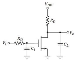
Figure P7.22
Expert Solution & Answer
Want to see the full answer?
Check out a sample textbook solution
Students have asked these similar questions
Problem 7.133(a): For the circuit shown below, let R1 = 106 kN, Rsig = 69 N, and RL
Rsig. Assume that
%3D
13 kN. Find the value of the bias current I in mA that results in Rin
the source provides a small signal vsie and that B = 100.
H
RL
R1
Rsig
Ria
8
In the self-bias circuit of Figure 7.80
a. Draw the transfer characteristic curve of the device.
b. Draw additional circuit equations on the same graph.
Find c.lDQ and VGSQ.
d. Calculate VDS , VD, VG, Vs.
...
VHDL Testbench Generate the following waveforms as part of a VHDL testbench using multiple processes. Note that cntr, and en signals are periodic signals and din and rst are not. Assume each time division is 10 ns. The ... represents the repeating pattern. Write your testbench as a parameterized waveform based on the parameter TD = 10 ns.
Chapter 7 Solutions
Microelectronics: Circuit Analysis and Design
Ch. 7 - (a) For the circuit shown in Figure 7.2, the...Ch. 7 - The circuit shown in Figure 7.10 has parameters of...Ch. 7 - For the equivalent circuit shown in Figure 7.13,...Ch. 7 - The equivalent circuit in Figure 7.14 has circuit...Ch. 7 - The parameters in the circuit shown in Figure 7.15...Ch. 7 - For the circuit shown in Figure 7.2 1(a), the...Ch. 7 - Consider the circuit shown in Figure 7.22(a). The...Ch. 7 - For the emitterfollower circuit shown in Figure...Ch. 7 - The circuit shown in Figure 7.27(a) has parameters...Ch. 7 - Consider the common-base circuit shown in Figure...
Ch. 7 - The commonemitter circuit shown in Figure 7.34...Ch. 7 - A bipolar transistor has parameters o=120 ,...Ch. 7 - Prob. 7.9EPCh. 7 - For the circuit in Figure 7.41(a), the parameters...Ch. 7 - A bipolar transistor is biased at ICQ=120A and its...Ch. 7 - For the transistor described in Example 7.9 and...Ch. 7 - The parameters of a bipolar transistor are: o=150...Ch. 7 - The parameters of an nchannel MOSFET are...Ch. 7 - For the circuit in Figure 7.55, the transistor...Ch. 7 - An nchannel MOSFET has parameters Kn=0.4mA/V2 ,...Ch. 7 - An nchannel MOSFET has a unitygain bandwidth of...Ch. 7 - For a MOSFET, assume that gm=1.2mA/V . The basic...Ch. 7 - The transistor in the circuit in Figure 7.60 has...Ch. 7 - Consider the commonbase circuit in Figure 7.64....Ch. 7 - The cascode circuit in Figure 7.65 has parameters...Ch. 7 - Prob. 7.12TYUCh. 7 - For the circuit in Figure 7.72, the transistor...Ch. 7 - Describe the general frequency response of an...Ch. 7 - Describe the general characteristics of the...Ch. 7 - Describe what is meant by a system transfer...Ch. 7 - What is the criterion that defines a corner, or...Ch. 7 - Describe what is meant by the phase of the...Ch. 7 - Describe the time constant technique for...Ch. 7 - Describe the general frequency response of a...Ch. 7 - Sketch the expanded hybrid model of the BJT.Ch. 7 - Prob. 9RQCh. 7 - Prob. 10RQCh. 7 - Prob. 11RQCh. 7 - Sketch the expanded smallsignal equivalent circuit...Ch. 7 - Define the cutoff frequency for a MOSFET.Ch. 7 - Prob. 14RQCh. 7 - Why is there not a Miller effect in a commonbase...Ch. 7 - Describe the configuration of a cascode amplifier.Ch. 7 - Why is the bandwidth of a cascode amplifier...Ch. 7 - Why is the bandwidth of the emitterfollower...Ch. 7 - Prob. 7.1PCh. 7 - Prob. 7.2PCh. 7 - Consider the circuit in Figure P7.3. (a) Derive...Ch. 7 - Consider the circuit in Figure P7.4 with a signal...Ch. 7 - Consider the circuit shown in Figure P7.5. (a)...Ch. 7 - A voltage transfer function is given by...Ch. 7 - Sketch the Bode magnitude plots for the following...Ch. 7 - (a) Determine the transfer function corresponding...Ch. 7 - Consider the circuit shown in Figure 7.15 with...Ch. 7 - For the circuit shown in Figure P7.12, the...Ch. 7 - The circuit shown in Figure 7.10 has parameters...Ch. 7 - The transistor shown in Figure P7.14 has...Ch. 7 - Consider the circuit shown in Figure P7.15. The...Ch. 7 - The transistor in the circuit shown in Figure...Ch. 7 - For the common-emitter circuit in Figure P7.17,...Ch. 7 - The transistor in the circuit in Figure P7.20 has...Ch. 7 - For the circuit in Figure P7.21, the transistor...Ch. 7 - (a) For the circuit shown in Figure P7.22, write...Ch. 7 - Consider the circuit shown in Figure P7.23. (a)...Ch. 7 - The parameters of the transistor in the circuit in...Ch. 7 - A capacitor is placed in parallel with RL in the...Ch. 7 - The parameters of the transistor in the circuit in...Ch. 7 - Prob. D7.27PCh. 7 - The circuit in Figure P7.28 is a simple output...Ch. 7 - Reconsider the circuit in Figure P728. The...Ch. 7 - Consider the circuit shown in Figure P7.32. The...Ch. 7 - The commonemitter circuit in Figure P7.35 has an...Ch. 7 - Consider the commonbase circuit in Figure 7.33 in...Ch. 7 - Prob. 7.39PCh. 7 - The parameters of the transistor in the circuit in...Ch. 7 - In the commonsource amplifier in Figure 7.25(a) in...Ch. 7 - A bipolar transistor has fT=4GHz , o=120 , and...Ch. 7 - A highfrequency bipolar transistor is biased at...Ch. 7 - (a) The frequency fT of a bipolar transistor is...Ch. 7 - The circuit in Figure P7.48 is a hybrid ...Ch. 7 - Consider the circuit in Figure P7.49. Calculate...Ch. 7 - A common-emitter equivalent circuit is shown in...Ch. 7 - For the common-emitter circuit in Figure 7.41(a)...Ch. 7 - For the commonemitter circuit in Figure P7.52,...Ch. 7 - Consider the circuit in Figure P7.52. The resistor...Ch. 7 - The parameters of the circuit shown in Figure...Ch. 7 - The parameters of an nchannel MOSFET are kn=80A/V2...Ch. 7 - Find fT for a MOSFET biased at IDQ=120A and...Ch. 7 - Fill in the missing parameter values in the...Ch. 7 - (a) An nchannel MOSFET has an electron mobility of...Ch. 7 - A commonsource equivalent circuit is shown in...Ch. 7 - Prob. 7.60PCh. 7 - The parameters of an ideal nchannel MOSFET are...Ch. 7 - Figure P7.62 shows the highfrequency equivalent...Ch. 7 - For the FET circuit in Figure P7.63, the...Ch. 7 - The midband voltage gain of a commonsource MOSFET...Ch. 7 - Prob. 7.65PCh. 7 - Prob. 7.67PCh. 7 - The bias voltages of the circuit shown in Figure...Ch. 7 - For the PMOS commonsource circuit shown in Figure...Ch. 7 - In the commonbase circuit shown in Figure P7.70,...Ch. 7 - Repeat Problem 7.70 for the commonbase circuit in...Ch. 7 - In the commongate circuit in Figure P7.72, the...
Knowledge Booster


Learn more about
Need a deep-dive on the concept behind this application? Look no further. Learn more about this topic, electrical-engineering and related others by exploring similar questions and additional content below.Similar questions
- A modulating signal f(t) has a maximum frequency of 18 kHz and peak value of 3volt, this signal is encoded using PCM. 1- Calculate the number of bits per sample if the number of levels is 130 2- Calculate the SNRQ if the average power of f(t) is 45 watt. 3- Calculate the minimum system bandwidth. e 7:20arrow_forwardBipolar junction transistors (BJTs) are considered “normally-off” devices, because their natural state with no signal applied to the base is no ........... between emitter and collector, like an open switch. * Your answer All field-effect transistors are unipolar rather than bipolar devices. That is, the main current through them is comprised either of ........... through an N-type semiconductor *arrow_forwardDoes a PCM signal have a smaller bandwidth? Why or Why not?arrow_forward
- In your own words, explain the Channel length modulation effect in MOSFET with a related graph and example circuit. [. a. b. In your own words, explain how MOSFET works as a Switch?arrow_forwardThis question would help revise concepts related to MOS device and basic circuit design. Please mark all correct answers to the following multiple choice questions. 1.1. Which of the following are true about MOSFET devices? (a) MOS stands for "Metallurgy Of Semiconductors" (b) MOSFET current conduction is due to drift phenomenon (c) An externally induced voltage at the gate is fundamental to inversion layer (d) Naming of "Source" and "Drain" regions are only dependent on aspect ratio 1.2. Which of the following are true about NMOS transistors (a) The threshold voltage can be positive or negative depending on geometry (b) Channel length modulation parameter (A) is always positive (c) Current flows from drain to source (d) Threshold voltage is a fixed value based on process, it cannot be changed by external voltages 1.3. In a MOS device (a) Cas and CGp both have both geometry and voltage dependencies (b) Cas is takes minimum value at saturation while CGD goes to maximum value (c) CoB and…arrow_forwardQ7: Explain constructional features of a MOSFET.arrow_forward
- 7. Although, geometrically no difference exists between the source and a drain of a MOSFET, drain and source terminals of a MOSFET are distinguished electrically. How are they distinguished in an nMOS transistor?arrow_forward(a) Design the circuit shown in Figure P7.18 such that Ipo = 0.8 mA, VDsQ = 3.2 V, Rin K, = 0.5 mA/V², VTN = 1.2 V, and A = 0. (b) What is the midband volt- age gain? (c) Determine the magnitude of the voltage gain at (i) f = 5 Hz, (ii) f = 14 Hz, and (iii) f = 25 Hz. (d) Sketch the Bode plot of the voltage gain magnitude and phase. 160 k2, and fr 16 Hz. The transistor parameters are ass VDD =9 V Rp R1 Rin 1 O vO Cc Rs = 0.5 k2 R2 Figure P7.18 ww wwarrow_forward1. Write an equation for an AM-modulated signal (AM-DSB), and explain the significance of all constants in the equation. Present a Simulink-style block diagram to implement an AM modulator.arrow_forward
- Q7. For the PMOS common-source circuit shown in Figure P7.69, the transistor parameters are: VTp = -2 V, K, Cgd = 3 pF. (a) Determine the upper 3 dB frequency. (b) What is the equiv- alent Miller capacitance? State any assumptions or approximations that you make. (c) Find the midband voltage gain. 1 mA/V², 1 = 0, Cgs = 15 pF, and +10 V Rs 0.5 kQ R=8 k2 Ci = 2 µF =Cs=10 µF wwHH R;=0.5 k2 Ce2 2 uF R3 = 22 k23 Rp=D 2 k2 RL= 5 k2 -10 V Figure P7.69 19 WW-arrow_forwardQ1. In AM the envelope of the modulated signal waveform is always * .symmetrical around the time axis True False Oarrow_forwardHow do we get the smal signal model and why CL and Cb doesn’t short the resistance because of the high frequency?arrow_forward
arrow_back_ios
SEE MORE QUESTIONS
arrow_forward_ios
Recommended textbooks for you
 Introductory Circuit Analysis (13th Edition)Electrical EngineeringISBN:9780133923605Author:Robert L. BoylestadPublisher:PEARSON
 Delmar's Standard Textbook Of ElectricityElectrical EngineeringISBN:9781337900348Author:Stephen L. HermanPublisher:Cengage Learning
 Programmable Logic ControllersElectrical EngineeringISBN:9780073373843Author:Frank D. PetruzellaPublisher:McGraw-Hill Education
 Fundamentals of Electric CircuitsElectrical EngineeringISBN:9780078028229Author:Charles K Alexander, Matthew SadikuPublisher:McGraw-Hill Education
 Electric Circuits. (11th Edition)Electrical EngineeringISBN:9780134746968Author:James W. Nilsson, Susan RiedelPublisher:PEARSON
 Engineering ElectromagneticsElectrical EngineeringISBN:9780078028151Author:Hayt, William H. (william Hart), Jr, BUCK, John A.Publisher:Mcgraw-hill Education,
Introductory Circuit Analysis (13th Edition)
Electrical Engineering
ISBN:9780133923605
Author:Robert L. Boylestad
Publisher:PEARSON
Delmar's Standard Textbook Of Electricity
Electrical Engineering
ISBN:9781337900348
Author:Stephen L. Herman
Publisher:Cengage Learning
Programmable Logic Controllers
Electrical Engineering
ISBN:9780073373843
Author:Frank D. Petruzella
Publisher:McGraw-Hill Education
Fundamentals of Electric Circuits
Electrical Engineering
ISBN:9780078028229
Author:Charles K Alexander, Matthew Sadiku
Publisher:McGraw-Hill Education
Electric Circuits. (11th Edition)
Electrical Engineering
ISBN:9780134746968
Author:James W. Nilsson, Susan Riedel
Publisher:PEARSON
Engineering Electromagnetics
Electrical Engineering
ISBN:9780078028151
Author:Hayt, William H. (william Hart), Jr, BUCK, John A.
Publisher:Mcgraw-hill Education,
Huffman Codes: An Information Theory Perspective; Author: Reducible;https://www.youtube.com/watch?v=B3y0RsVCyrw;License: Standard Youtube License