
Electronics Fundamentals: Circuits, Devices & Applications
8th Edition
ISBN: 9780135072950
Author: Thomas L. Floyd, David Buchla
Publisher: Prentice Hall
expand_more
expand_more
format_list_bulleted
Concept explainers
Videos
Textbook Question
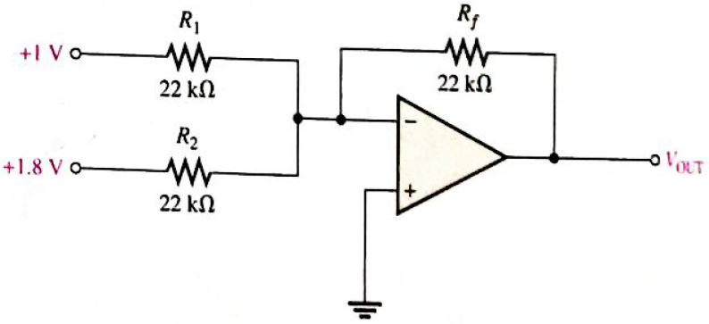
Chapter 19, Problem 6P
Find the value of
Expert Solution & Answer
Want to see the full answer?
Check out a sample textbook solution
Students have asked these similar questions
The input signal in figure shown below is applied to the comparator in the
figure.
Draw the output signal showing its proper relationship to the input signal.
Assume the maximum output levels of the comparator are (+/-)14 V.
A
Vin 0-
5 V-
-5 V-
+15 V
R₁
8.2 ΚΩ
R₂
1.0 ΚΩ
550
www
V
out
Assume that the input voltage is 19.7V. The current through the
mA.
feedback resistor when the switch is closed is
(Write the exact answer. Do not round off.)
R3= 100kn
IN O
GAIN
SELECT
R, = 100 ΚΩ
74 HC 4016
'S
ESM
R₂ =
100 ΚΩ
+
OUT
The following transducer is used to measure the temperature.
a.
Bourdon tube
b.
Strain Gauge
c.
Bellows
d.
RTD
Chapter 19 Solutions
Electronics Fundamentals: Circuits, Devices & Applications
Ch. 19 - A comparator will have a positive output whenever...Ch. 19 - Prob. 2TFQCh. 19 - Prob. 3TFQCh. 19 - Prob. 4TFQCh. 19 - Prob. 5TFQCh. 19 - The output of a Wien-bridge oscillator is a...Ch. 19 - A Wien-bridge oscillator uses both positive and...Ch. 19 - A two-pole filter has a maximum roll-off rate of...Ch. 19 - Prob. 9TFQCh. 19 - Prob. 10TFQ
Ch. 19 - Prob. 1STCh. 19 - To use a comparator for zero-level detection, the...Ch. 19 - Prob. 3STCh. 19 - Prob. 4STCh. 19 - The gain of the amplifier in Question 4 is -1 -2.2...Ch. 19 - To convert a summing amplifier to an averaging...Ch. 19 - Prob. 7STCh. 19 - Prob. 8STCh. 19 - The feedback path in an op-amp differentiator...Ch. 19 - Prob. 10STCh. 19 - Prob. 11STCh. 19 - Prob. 12STCh. 19 - Determine the output level (maximum positive or...Ch. 19 - A certain op-amp has open-loop gain of 80,000. The...Ch. 19 - Prob. 3PCh. 19 - Determine the output voltage for each circuit in...Ch. 19 - Determine the following in Figure 19—62: VR1 and...Ch. 19 - Find the value of Rf necessary to produce an...Ch. 19 - Find the output voltage when the input voltages...Ch. 19 - Determine the values of the input resistors...Ch. 19 - Determine the rate of change of the output voltage...Ch. 19 - A triangular waveform is applied to the input of...Ch. 19 - Prob. 11PCh. 19 - Calculate the resonant frequency of a lead-lag...Ch. 19 - Determine the JFET drain-to-source resistance in...Ch. 19 - Explain the purpose of D1 in Figure 19-66.Ch. 19 - Find the frequency of oscillation for the...Ch. 19 - What type of signal does the circuit in Figure...Ch. 19 - Prob. 17PCh. 19 - Determine the number of poles in each active...Ch. 19 - Calculate the critical frequencies for the filters...Ch. 19 - Determine the bandwidth and center frequency of...Ch. 19 - Determine the output voltage for the series...Ch. 19 - If R3 in figure 19-70 is doubled, what happens to...Ch. 19 - Prob. 23PCh. 19 - A series voltage regulator with constant-current...Ch. 19 - If R4 (determined in Problem 24) is halved, what...Ch. 19 - In the shunt regulator of Figure 19-72, when the...Ch. 19 - Assume that IL remains constant and VIN increases...Ch. 19 - Open file P19-29; files are found at...Ch. 19 - Open file P19-30 and determine if there is a...
Knowledge Booster


Learn more about
Need a deep-dive on the concept behind this application? Look no further. Learn more about this topic, electrical-engineering and related others by exploring similar questions and additional content below.Similar questions
- In a flash A/D converter, the priority * encoder is used to select the first input O select the highest value input select the lowest value input O select the last input Oarrow_forwardQ1 and Q2 are biased such that max swing at the output is possible. Use VBE,ON = 0.6V, VBE,oN = 0.2V, Iş = 456f A ,and VA = 180V for Q1 and Q2 Find Ig and ß R1 27k Q1 R2 7.5k Q2 R3 27k 12V 12Varrow_forwardSAMPLING CLOCK ANALOG INPUT +V REF 1.5R R R PRIORITY ENCODER DIGITAL R OU TPUT OUTPUT AND LATCH LATCH R R 0.5R If R=5kOhms and Vref=5V, what is the voltage at the node that joins the 1.5R resistor and the top R resistor? /4arrow_forward
- Dead space is defined as the range of different output values over which there is no change in input value. Select one: O True O Falsearrow_forwardVcc 14 13 12 12 34 5|67 The following Ic diagram is for GND O a. AND 7421 Dual 4-input O b. NOR 7427 Triple 3-input O C. AND 7411 Triple 3-input O d. NOR 7402 Quad 2-inputarrow_forwardIdentify names of functional elements of the given block diagram. Strain Resistance Millivolts Volts Strain Deflection Amplifier ADC gauge bridgearrow_forward
- In a combinational circuit, the output at any time depends only on the a) Voltage at that time. b) Intermediate values c) Input values d) Clock pulsesarrow_forwardNumber of IC required to implement min-term of borrow output of half subtractor? Options A-1 B-2 C-3 D-4arrow_forwardAn A/D converter has the following circuit on its input port. a. bandpass filter b. high pass filter c. Sample and Hold circuit d. Low pass filter e. Amplifierarrow_forward
- For the given circuit, what is the minimum peak value of the output waveform if the input waveform is 10V square wave with switching time of 1 second? Assume that the input switches between +10V and -10V DC levels. O - 10 V O - 20 V O ov O -5 Varrow_forwardA fifth order active HPF have a roll-off rate of * -50 dB/decade O -100 dB/ decade -40 dB/ decade O -20 dB/ decadearrow_forwardAn op-amp is usually a differential amplifier having O Dual input and only one output Single input and two outputs always O Single input and single output always O Unbalanced input and two outputs always um umptoarrow_forward
arrow_back_ios
SEE MORE QUESTIONS
arrow_forward_ios
Recommended textbooks for you
 Introductory Circuit Analysis (13th Edition)Electrical EngineeringISBN:9780133923605Author:Robert L. BoylestadPublisher:PEARSON
 Delmar's Standard Textbook Of ElectricityElectrical EngineeringISBN:9781337900348Author:Stephen L. HermanPublisher:Cengage Learning
 Programmable Logic ControllersElectrical EngineeringISBN:9780073373843Author:Frank D. PetruzellaPublisher:McGraw-Hill Education
 Fundamentals of Electric CircuitsElectrical EngineeringISBN:9780078028229Author:Charles K Alexander, Matthew SadikuPublisher:McGraw-Hill Education
 Electric Circuits. (11th Edition)Electrical EngineeringISBN:9780134746968Author:James W. Nilsson, Susan RiedelPublisher:PEARSON
 Engineering ElectromagneticsElectrical EngineeringISBN:9780078028151Author:Hayt, William H. (william Hart), Jr, BUCK, John A.Publisher:Mcgraw-hill Education,
Introductory Circuit Analysis (13th Edition)
Electrical Engineering
ISBN:9780133923605
Author:Robert L. Boylestad
Publisher:PEARSON
Delmar's Standard Textbook Of Electricity
Electrical Engineering
ISBN:9781337900348
Author:Stephen L. Herman
Publisher:Cengage Learning
Programmable Logic Controllers
Electrical Engineering
ISBN:9780073373843
Author:Frank D. Petruzella
Publisher:McGraw-Hill Education
Fundamentals of Electric Circuits
Electrical Engineering
ISBN:9780078028229
Author:Charles K Alexander, Matthew Sadiku
Publisher:McGraw-Hill Education
Electric Circuits. (11th Edition)
Electrical Engineering
ISBN:9780134746968
Author:James W. Nilsson, Susan Riedel
Publisher:PEARSON
Engineering Electromagnetics
Electrical Engineering
ISBN:9780078028151
Author:Hayt, William H. (william Hart), Jr, BUCK, John A.
Publisher:Mcgraw-hill Education,
Designing a sample & hold-circuit from scratch; Author: Moritz Klein;https://www.youtube.com/watch?v=kIJqzkRe4do;License: Standard Youtube License