
Electronics Fundamentals: Circuits, Devices & Applications
8th Edition
ISBN: 9780135072950
Author: Thomas L. Floyd, David Buchla
Publisher: Prentice Hall
expand_more
expand_more
format_list_bulleted
Concept explainers
Videos
Textbook Question
Chapter 19, Problem 15P
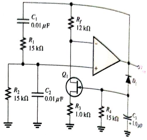
Find the frequency of oscillation for the Wien-bridge oscillator in Figure 19-66
Expert Solution & Answer
Want to see the full answer?
Check out a sample textbook solution
Students have asked these similar questions
hil
E
3. Identify the type of input mode for each op-amp in Figure 12-61.
Val
Figure 12-61
4. A certain op-amp has a CMRR of 250,000. Convert this to decibels.
▸
Determine the period and frequency of oscillation for an astable
multivibrator with component values R =2 k2, R2 =10 k2, C =0.01 uF and
C =0.05 u F.
%3D
%3D
Change the MOD-8 counter in Figure to a MOD-16 counter, and
connect the MSB to the multiplexer E input. Draw the Z waveform.
1 ΚΩ
+Vcc W
13
1₂
lo
Eight-input
multiplexer
74HC151
SSS
17
$₂
S₁
So
MOD-8 CLK-
counter
•JMM
Chapter 19 Solutions
Electronics Fundamentals: Circuits, Devices & Applications
Ch. 19 - A comparator will have a positive output whenever...Ch. 19 - Prob. 2TFQCh. 19 - Prob. 3TFQCh. 19 - Prob. 4TFQCh. 19 - Prob. 5TFQCh. 19 - The output of a Wien-bridge oscillator is a...Ch. 19 - A Wien-bridge oscillator uses both positive and...Ch. 19 - A two-pole filter has a maximum roll-off rate of...Ch. 19 - Prob. 9TFQCh. 19 - Prob. 10TFQ
Ch. 19 - Prob. 1STCh. 19 - To use a comparator for zero-level detection, the...Ch. 19 - Prob. 3STCh. 19 - Prob. 4STCh. 19 - The gain of the amplifier in Question 4 is -1 -2.2...Ch. 19 - To convert a summing amplifier to an averaging...Ch. 19 - Prob. 7STCh. 19 - Prob. 8STCh. 19 - The feedback path in an op-amp differentiator...Ch. 19 - Prob. 10STCh. 19 - Prob. 11STCh. 19 - Prob. 12STCh. 19 - Determine the output level (maximum positive or...Ch. 19 - A certain op-amp has open-loop gain of 80,000. The...Ch. 19 - Prob. 3PCh. 19 - Determine the output voltage for each circuit in...Ch. 19 - Determine the following in Figure 19—62: VR1 and...Ch. 19 - Find the value of Rf necessary to produce an...Ch. 19 - Find the output voltage when the input voltages...Ch. 19 - Determine the values of the input resistors...Ch. 19 - Determine the rate of change of the output voltage...Ch. 19 - A triangular waveform is applied to the input of...Ch. 19 - Prob. 11PCh. 19 - Calculate the resonant frequency of a lead-lag...Ch. 19 - Determine the JFET drain-to-source resistance in...Ch. 19 - Explain the purpose of D1 in Figure 19-66.Ch. 19 - Find the frequency of oscillation for the...Ch. 19 - What type of signal does the circuit in Figure...Ch. 19 - Prob. 17PCh. 19 - Determine the number of poles in each active...Ch. 19 - Calculate the critical frequencies for the filters...Ch. 19 - Determine the bandwidth and center frequency of...Ch. 19 - Determine the output voltage for the series...Ch. 19 - If R3 in figure 19-70 is doubled, what happens to...Ch. 19 - Prob. 23PCh. 19 - A series voltage regulator with constant-current...Ch. 19 - If R4 (determined in Problem 24) is halved, what...Ch. 19 - In the shunt regulator of Figure 19-72, when the...Ch. 19 - Assume that IL remains constant and VIN increases...Ch. 19 - Open file P19-29; files are found at...Ch. 19 - Open file P19-30 and determine if there is a...
Knowledge Booster


Learn more about
Need a deep-dive on the concept behind this application? Look no further. Learn more about this topic, electrical-engineering and related others by exploring similar questions and additional content below.Similar questions
- The frequency of oscillation of the oscillator shown in below figure is C₁ = 10pF HE + L=5μH vooro C₂=10pF HEarrow_forwardA boost converter with an input voltage of 5 V dc and an output voltage of 8 V dc will have a duty cycle ofarrow_forwarddesign a triangular wave oscillator with oscillation frequency of (50 KHz) andtriangle wave has Vp-p = 6v with Vcc= 18v draw circuit and output waves (vo1 andVo2)arrow_forward
- Which of the following is not true regarding clamper? A positive clamper adds a positive DC voltage To reduce level shift, reduce the RC value O A clamper can also be called as a voltage restorer O Negative clamper will clamp the positive peak of output to the reference voltagearrow_forwardA certain lead-lag network has all resistors equal and all capacitors equal. What is the output voltage if the input voltage is equal to 10 Vrms?arrow_forwardơ: Determine the circuit type and caleulate the output voltage, draw the output waveform. ISV D,=Ge D,=Ge REIKO R=IKO -5Varrow_forward
- For an SCR di/dt protection is achieved through the use of: O Rin series with SCR O RL in series with SCR O Lin series with SCR O None of thesearrow_forwardFor the given circuit, what is the minimum peak value of the output waveform if the input waveform is 10V square wave with switching time of 1 second? Assume that the input switches between +10V and -10V DC levels. O - 10 V O - 20 V O ov O -5 Varrow_forwardWhat is the different between self bias and fixed bias and follwer in jfetarrow_forward
- The following transducer is used to measure the temperature. a. Bourdon tube b. Strain Gauge c. Bellows d. RTDarrow_forwardPart C: Voltage Regulators 1. Determine the output voltage for the series regulator in Figure 17-46. +12 Vo R₁ 10 kn 2.4 V Q₁ o VOUT R₂ 5.6 kn www R₂ 2.2kQarrow_forwardthe correct name of this oscillator is * R1 Tank Circuit crystal RC LC Hartley K Feedback 2 ww www R3 R4 ww +V v Output Ovarrow_forward
arrow_back_ios
SEE MORE QUESTIONS
arrow_forward_ios
Recommended textbooks for you
 Introductory Circuit Analysis (13th Edition)Electrical EngineeringISBN:9780133923605Author:Robert L. BoylestadPublisher:PEARSON
 Delmar's Standard Textbook Of ElectricityElectrical EngineeringISBN:9781337900348Author:Stephen L. HermanPublisher:Cengage Learning
 Programmable Logic ControllersElectrical EngineeringISBN:9780073373843Author:Frank D. PetruzellaPublisher:McGraw-Hill Education
 Fundamentals of Electric CircuitsElectrical EngineeringISBN:9780078028229Author:Charles K Alexander, Matthew SadikuPublisher:McGraw-Hill Education
 Electric Circuits. (11th Edition)Electrical EngineeringISBN:9780134746968Author:James W. Nilsson, Susan RiedelPublisher:PEARSON
 Engineering ElectromagneticsElectrical EngineeringISBN:9780078028151Author:Hayt, William H. (william Hart), Jr, BUCK, John A.Publisher:Mcgraw-hill Education,
Introductory Circuit Analysis (13th Edition)
Electrical Engineering
ISBN:9780133923605
Author:Robert L. Boylestad
Publisher:PEARSON
Delmar's Standard Textbook Of Electricity
Electrical Engineering
ISBN:9781337900348
Author:Stephen L. Herman
Publisher:Cengage Learning
Programmable Logic Controllers
Electrical Engineering
ISBN:9780073373843
Author:Frank D. Petruzella
Publisher:McGraw-Hill Education
Fundamentals of Electric Circuits
Electrical Engineering
ISBN:9780078028229
Author:Charles K Alexander, Matthew Sadiku
Publisher:McGraw-Hill Education
Electric Circuits. (11th Edition)
Electrical Engineering
ISBN:9780134746968
Author:James W. Nilsson, Susan Riedel
Publisher:PEARSON
Engineering Electromagnetics
Electrical Engineering
ISBN:9780078028151
Author:Hayt, William H. (william Hart), Jr, BUCK, John A.
Publisher:Mcgraw-hill Education,
Designing a sample & hold-circuit from scratch; Author: Moritz Klein;https://www.youtube.com/watch?v=kIJqzkRe4do;License: Standard Youtube License