
Electronics Fundamentals: Circuits, Devices & Applications
8th Edition
ISBN: 9780135072950
Author: Thomas L. Floyd, David Buchla
Publisher: Prentice Hall
expand_more
expand_more
format_list_bulleted
Concept explainers
Videos
Textbook Question
Chapter 19, Problem 9P
Determine the rate of change of the output voltage in response to the step input to the ideal integrator in Figure 19-64.
Expert Solution & Answer
Want to see the full answer?
Check out a sample textbook solution
Students have asked these similar questions
Ry= 100ka
C= OL047pF
RI
10kO
15V
R2
10k2,
1. Mention the phase difference between the input and output waveforms?
2. Calculate the Vout of the output waveforms?
3. Calculate the comer frequency of output waveform?
4. Draw the input and output waveforms of integrator.
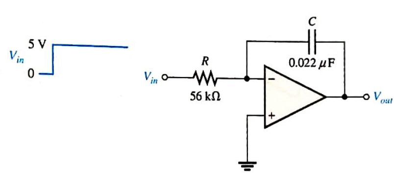
A square waveform is applied to the input of the integrator circuit. Determine the rate of change
of the output voltage in response to the step input to the circuit as shown. Also determine the
output voltage and sketch the output waveform in relation to the input. circuit.
5 V
0.022 µF
Vin 0-
56 kN
out
Calculate the pulse width T of the circuit. Plot Vo
Opamp is 741 with Vcc = 15V and VEE = -15V
Rin = 2M ohm
Rout = 75 ohm
Open-loop Gain = 200000
Chapter 19 Solutions
Electronics Fundamentals: Circuits, Devices & Applications
Ch. 19 - A comparator will have a positive output whenever...Ch. 19 - Prob. 2TFQCh. 19 - Prob. 3TFQCh. 19 - Prob. 4TFQCh. 19 - Prob. 5TFQCh. 19 - The output of a Wien-bridge oscillator is a...Ch. 19 - A Wien-bridge oscillator uses both positive and...Ch. 19 - A two-pole filter has a maximum roll-off rate of...Ch. 19 - Prob. 9TFQCh. 19 - Prob. 10TFQ
Ch. 19 - Prob. 1STCh. 19 - To use a comparator for zero-level detection, the...Ch. 19 - Prob. 3STCh. 19 - Prob. 4STCh. 19 - The gain of the amplifier in Question 4 is -1 -2.2...Ch. 19 - To convert a summing amplifier to an averaging...Ch. 19 - Prob. 7STCh. 19 - Prob. 8STCh. 19 - The feedback path in an op-amp differentiator...Ch. 19 - Prob. 10STCh. 19 - Prob. 11STCh. 19 - Prob. 12STCh. 19 - Determine the output level (maximum positive or...Ch. 19 - A certain op-amp has open-loop gain of 80,000. The...Ch. 19 - Prob. 3PCh. 19 - Determine the output voltage for each circuit in...Ch. 19 - Determine the following in Figure 19—62: VR1 and...Ch. 19 - Find the value of Rf necessary to produce an...Ch. 19 - Find the output voltage when the input voltages...Ch. 19 - Determine the values of the input resistors...Ch. 19 - Determine the rate of change of the output voltage...Ch. 19 - A triangular waveform is applied to the input of...Ch. 19 - Prob. 11PCh. 19 - Calculate the resonant frequency of a lead-lag...Ch. 19 - Determine the JFET drain-to-source resistance in...Ch. 19 - Explain the purpose of D1 in Figure 19-66.Ch. 19 - Find the frequency of oscillation for the...Ch. 19 - What type of signal does the circuit in Figure...Ch. 19 - Prob. 17PCh. 19 - Determine the number of poles in each active...Ch. 19 - Calculate the critical frequencies for the filters...Ch. 19 - Determine the bandwidth and center frequency of...Ch. 19 - Determine the output voltage for the series...Ch. 19 - If R3 in figure 19-70 is doubled, what happens to...Ch. 19 - Prob. 23PCh. 19 - A series voltage regulator with constant-current...Ch. 19 - If R4 (determined in Problem 24) is halved, what...Ch. 19 - In the shunt regulator of Figure 19-72, when the...Ch. 19 - Assume that IL remains constant and VIN increases...Ch. 19 - Open file P19-29; files are found at...Ch. 19 - Open file P19-30 and determine if there is a...
Knowledge Booster


Learn more about
Need a deep-dive on the concept behind this application? Look no further. Learn more about this topic, electrical-engineering and related others by exploring similar questions and additional content below.Similar questions
- How does the output voltage vary when the capacitance is doubled in integrator operational amplifier citcuit?arrow_forwardWhat is the relationship between the output voltage and the capacitive reactance of an integrator? Cannot be determined Inversely proportional Directly proportional No relationship at allarrow_forwardFor an op-amp integrator with R = 100KOhms, C= 10UF and a sine wave input signal of 10 sinot (V), the output waveform is (V). +10 sinwt O -10 sinwt +10 coswt -10 coswtarrow_forward
- 1. What is the effect of the time constant of the integrator on the frequency of oscillation? 2. What is the effect of changing B on the frequency of oscillation?arrow_forwardThe type of the feedback in this circuit is: VDO M₂Vb Rs Vino W (10 -0 M₁ Select one: O a series series feedback Ob shunt-series feedback Oc series shunt feedback Od none of these Voutarrow_forwardIntegrator with input of constant current gives sine a. b triangular wave pulse C. d. Square wavearrow_forward
- 18. Determine the approximate values for each of the following quantities in Figure 12-67. (a) (b) ! (c) Vout (d) closed-loop gain FIGURE 12-67 R 22 kfl R, 2.2 klarrow_forwardon For the circuit shown below, if the delay time of each stage is considered to be 50 ns, the oscillation frequency at the output will be almost MHZ HE VDD Voutarrow_forwardCalculate the ideal gain of the integrator circuit of figure 1 at 100 Hzarrow_forward
- A square waveform is applied to the input of the integrator circuit. Determine the rate of change of the outputvoltage in response to the step input to the circuit as shown. Also deterrmine the output voltage and sketch the output waveform in relation to the input. circuit. 5 V R 0.022 uF V 0 56 kfarrow_forwardVoltage Gain = Vo/ Vin. One of the assumptions made for an ideal opamp is that its open loop voltage gain is O infinite O low O zero O 1arrow_forwardProblem 2: Connect the following components to build an integrator. A19PX I 531 OUT1 Vcc IN1 (-) 2 7 OUT2 IN1 (+) 3. IN2 (-) GND IN2 (+)arrow_forward
arrow_back_ios
SEE MORE QUESTIONS
arrow_forward_ios
Recommended textbooks for you
 Introductory Circuit Analysis (13th Edition)Electrical EngineeringISBN:9780133923605Author:Robert L. BoylestadPublisher:PEARSON
 Delmar's Standard Textbook Of ElectricityElectrical EngineeringISBN:9781337900348Author:Stephen L. HermanPublisher:Cengage Learning
 Programmable Logic ControllersElectrical EngineeringISBN:9780073373843Author:Frank D. PetruzellaPublisher:McGraw-Hill Education
 Fundamentals of Electric CircuitsElectrical EngineeringISBN:9780078028229Author:Charles K Alexander, Matthew SadikuPublisher:McGraw-Hill Education
 Electric Circuits. (11th Edition)Electrical EngineeringISBN:9780134746968Author:James W. Nilsson, Susan RiedelPublisher:PEARSON
 Engineering ElectromagneticsElectrical EngineeringISBN:9780078028151Author:Hayt, William H. (william Hart), Jr, BUCK, John A.Publisher:Mcgraw-hill Education,
Introductory Circuit Analysis (13th Edition)
Electrical Engineering
ISBN:9780133923605
Author:Robert L. Boylestad
Publisher:PEARSON
Delmar's Standard Textbook Of Electricity
Electrical Engineering
ISBN:9781337900348
Author:Stephen L. Herman
Publisher:Cengage Learning
Programmable Logic Controllers
Electrical Engineering
ISBN:9780073373843
Author:Frank D. Petruzella
Publisher:McGraw-Hill Education
Fundamentals of Electric Circuits
Electrical Engineering
ISBN:9780078028229
Author:Charles K Alexander, Matthew Sadiku
Publisher:McGraw-Hill Education
Electric Circuits. (11th Edition)
Electrical Engineering
ISBN:9780134746968
Author:James W. Nilsson, Susan Riedel
Publisher:PEARSON
Engineering Electromagnetics
Electrical Engineering
ISBN:9780078028151
Author:Hayt, William H. (william Hart), Jr, BUCK, John A.
Publisher:Mcgraw-hill Education,
Differential Amplifiers Made Easy; Author: The AudioPhool;https://www.youtube.com/watch?v=Mcxpn2HMgtU;License: Standard Youtube License