
Electronics Fundamentals: Circuits, Devices & Applications
8th Edition
ISBN: 9780135072950
Author: Thomas L. Floyd, David Buchla
Publisher: Prentice Hall
expand_more
expand_more
format_list_bulleted
Videos
Textbook Question
Chapter 19, Problem 20P
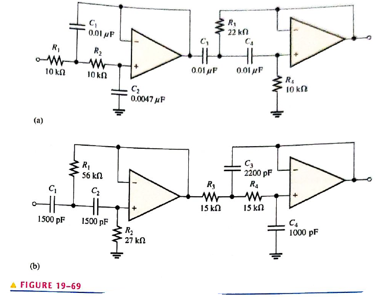
Determine the bandwidth and center frequency of each filter Figure
Expert Solution & Answer
Want to see the full answer?
Check out a sample textbook solution
Students have asked these similar questions
Determine the output voltage in V with VA-4.4 V, VB-2.54 V , RA=4 kohm, RB-4 kohm, RC=6 kohm and RD=6 kohm
RC
RA
VB
U4
• Vout
RB
VA
OPAMP
RD
Questions Filter (5)
INTEGRO-DIFFERENTIAL
1. y" + 5y' - 4y = 0
Determine the break frequency in KHZ of the RC low-pass circuit below. Assume that Resistor value is 3 KQ and Capacitr value is
0.02uF.
Chapter 19 Solutions
Electronics Fundamentals: Circuits, Devices & Applications
Ch. 19 - A comparator will have a positive output whenever...Ch. 19 - Prob. 2TFQCh. 19 - Prob. 3TFQCh. 19 - Prob. 4TFQCh. 19 - Prob. 5TFQCh. 19 - The output of a Wien-bridge oscillator is a...Ch. 19 - A Wien-bridge oscillator uses both positive and...Ch. 19 - A two-pole filter has a maximum roll-off rate of...Ch. 19 - Prob. 9TFQCh. 19 - Prob. 10TFQ
Ch. 19 - Prob. 1STCh. 19 - To use a comparator for zero-level detection, the...Ch. 19 - Prob. 3STCh. 19 - Prob. 4STCh. 19 - The gain of the amplifier in Question 4 is -1 -2.2...Ch. 19 - To convert a summing amplifier to an averaging...Ch. 19 - Prob. 7STCh. 19 - Prob. 8STCh. 19 - The feedback path in an op-amp differentiator...Ch. 19 - Prob. 10STCh. 19 - Prob. 11STCh. 19 - Prob. 12STCh. 19 - Determine the output level (maximum positive or...Ch. 19 - A certain op-amp has open-loop gain of 80,000. The...Ch. 19 - Prob. 3PCh. 19 - Determine the output voltage for each circuit in...Ch. 19 - Determine the following in Figure 19—62: VR1 and...Ch. 19 - Find the value of Rf necessary to produce an...Ch. 19 - Find the output voltage when the input voltages...Ch. 19 - Determine the values of the input resistors...Ch. 19 - Determine the rate of change of the output voltage...Ch. 19 - A triangular waveform is applied to the input of...Ch. 19 - Prob. 11PCh. 19 - Calculate the resonant frequency of a lead-lag...Ch. 19 - Determine the JFET drain-to-source resistance in...Ch. 19 - Explain the purpose of D1 in Figure 19-66.Ch. 19 - Find the frequency of oscillation for the...Ch. 19 - What type of signal does the circuit in Figure...Ch. 19 - Prob. 17PCh. 19 - Determine the number of poles in each active...Ch. 19 - Calculate the critical frequencies for the filters...Ch. 19 - Determine the bandwidth and center frequency of...Ch. 19 - Determine the output voltage for the series...Ch. 19 - If R3 in figure 19-70 is doubled, what happens to...Ch. 19 - Prob. 23PCh. 19 - A series voltage regulator with constant-current...Ch. 19 - If R4 (determined in Problem 24) is halved, what...Ch. 19 - In the shunt regulator of Figure 19-72, when the...Ch. 19 - Assume that IL remains constant and VIN increases...Ch. 19 - Open file P19-29; files are found at...Ch. 19 - Open file P19-30 and determine if there is a...
Knowledge Booster


Learn more about
Need a deep-dive on the concept behind this application? Look no further. Learn more about this topic, electrical-engineering and related others by exploring similar questions and additional content below.Similar questions
- A series resonant filter can be made into a:a. low-pass filterb. high-pass filterc. band-pass filterd. none of the abovearrow_forwardAn RC high pass filter consists of a 1000 Ohm resistor, what is the value of C so that the cut off frequency is 10 KHz Oa. None of the answers b. 0.01 nF Oc. 100 nF O d. 16 nFarrow_forward11. In a certain low-pass filter, XC-500 and R=2.2 k. What is the output voltage (VoutVout) when the input is 10 V rms?arrow_forward
- For the given circuit below R =4.7kohm , L = 22 mH C =33nF Determine: a) Determine the upper cutoff frequency and the lower cutoff frequency in kHz. b) Determine the center frequency in kHz c) Does this circuit function as a band-pass or a band-stop filter?arrow_forwardIf the gain is minimum at the center frequency, the filter is * LPF О BSF BPF HPFarrow_forwardIt is the frequency at which the magnitude of the output becomes 0.707 of the maximum. A) CUT OFF FREQUENCY B) RESONANT FREQUENCY C) UPPER FREQUENCY D) LOWER FREQUENCYarrow_forward
- Q3/ Determine the centre frequency, maximum gain, bandwidth and type filter for the circuiting figure. 1 k Ohm 0.022 uF 0.047 uF 0.047 uF VI 1 k Ohm 1 k Ohm HE HE Vo HOhm 560 Ohm 1 K 560 Ohm 0.022 uF 1 k Ohm 1 k Ohmarrow_forwardWhat will be the output voltage of Low pass filter if the resistance value is 3.7 kilo ohm, capacitance value is 20 nano farad and input voltage applied is 8.6V. Frequency is 500 Hz.arrow_forwardA low pass filter has a cut-off frequency of 200 Hz while a high pass filter has a cut-off frequency of 20 kHz are connected in parallel to form a bandstop filter. The center frequency and bandwidth is O 2 kHz, 9.9 kHz O 1 kHz, 19.8 kHz 1 kHz, 9.9 kHz 2kHz, 19.8 kHzarrow_forward
- Q3/ Determine the centre frequency, maximum gain, bandwidth and type filter for the circuiting figure. 1 kOhm 0.022 UF HH 0.047 uF 0.047 UF 1 k Ohm 1 kOhm vo HH HH 560 Ohm 1 Hohm 560 Ohm 0.022 UF 1 k Ohm 1 kOhmarrow_forwardDetermine the center frequency, maximum gain and bandwidth for the filter in figure below. C 0.01 R2 C2 180 kN R1 Vin 68 kN 0.01 µF Vout R3 2.7 kN Answer: fo = 736 Hz, Ao = 1.32, BW = 177 Hzarrow_forwardWhat is the high pass filter cutoff frequency of the circuit R1= 54 Q, R2 = 261 Q, RF = 332 Q, RG = 8560 Q, C1 = 0.25 uF, C2 = 89 uF. Note: No need to place the unit, express your answer in Hz, two decimal places. ww m RG RF Vout ww ww RG RF R2 Vin C1 fin R1 + C2 +arrow_forward
arrow_back_ios
SEE MORE QUESTIONS
arrow_forward_ios
Recommended textbooks for you
 Introductory Circuit Analysis (13th Edition)Electrical EngineeringISBN:9780133923605Author:Robert L. BoylestadPublisher:PEARSON
 Delmar's Standard Textbook Of ElectricityElectrical EngineeringISBN:9781337900348Author:Stephen L. HermanPublisher:Cengage Learning
 Programmable Logic ControllersElectrical EngineeringISBN:9780073373843Author:Frank D. PetruzellaPublisher:McGraw-Hill Education
 Fundamentals of Electric CircuitsElectrical EngineeringISBN:9780078028229Author:Charles K Alexander, Matthew SadikuPublisher:McGraw-Hill Education
 Electric Circuits. (11th Edition)Electrical EngineeringISBN:9780134746968Author:James W. Nilsson, Susan RiedelPublisher:PEARSON
 Engineering ElectromagneticsElectrical EngineeringISBN:9780078028151Author:Hayt, William H. (william Hart), Jr, BUCK, John A.Publisher:Mcgraw-hill Education,
Introductory Circuit Analysis (13th Edition)
Electrical Engineering
ISBN:9780133923605
Author:Robert L. Boylestad
Publisher:PEARSON
Delmar's Standard Textbook Of Electricity
Electrical Engineering
ISBN:9781337900348
Author:Stephen L. Herman
Publisher:Cengage Learning
Programmable Logic Controllers
Electrical Engineering
ISBN:9780073373843
Author:Frank D. Petruzella
Publisher:McGraw-Hill Education
Fundamentals of Electric Circuits
Electrical Engineering
ISBN:9780078028229
Author:Charles K Alexander, Matthew Sadiku
Publisher:McGraw-Hill Education
Electric Circuits. (11th Edition)
Electrical Engineering
ISBN:9780134746968
Author:James W. Nilsson, Susan Riedel
Publisher:PEARSON
Engineering Electromagnetics
Electrical Engineering
ISBN:9780078028151
Author:Hayt, William H. (william Hart), Jr, BUCK, John A.
Publisher:Mcgraw-hill Education,
Inductors Explained - The basics how inductors work working principle; Author: The Engineering Mindset;https://www.youtube.com/watch?v=KSylo01n5FY;License: Standard Youtube License