
Electronics Fundamentals: Circuits, Devices & Applications
8th Edition
ISBN: 9780135072950
Author: Thomas L. Floyd, David Buchla
Publisher: Prentice Hall
expand_more
expand_more
format_list_bulleted
Concept explainers
Videos
Textbook Question
Chapter 19, Problem 22P
If
Expert Solution & Answer
Want to see the full answer?
Check out a sample textbook solution
Students have asked these similar questions
Determine the output voltage in V WHEN R1= 8kiloohms , r3= 7kohm ,r5=13kohm r7= 120kohms reference voltage of 2.5V and input volatge Vi=2.592V
Clipper Circuit
5. At OV, what is the output voltage?
O ov
2V
O 2v
Vin
Vout
Ik
OV
O 2V
O 3v
6. At +20V, what is the output 7. At -5V, what is the output voltage?
voltage?
O 7V
O 20V
O 3V
O ov
O 22V
O 15V
O 18V
Voltage multipliers take an ac input voltage, and provide
an ac output voltage that is a multiple of the input
an ac output twice the input
none of these
a dc output voltage that is a multiple of the input
Chapter 19 Solutions
Electronics Fundamentals: Circuits, Devices & Applications
Ch. 19 - A comparator will have a positive output whenever...Ch. 19 - Prob. 2TFQCh. 19 - Prob. 3TFQCh. 19 - Prob. 4TFQCh. 19 - Prob. 5TFQCh. 19 - The output of a Wien-bridge oscillator is a...Ch. 19 - A Wien-bridge oscillator uses both positive and...Ch. 19 - A two-pole filter has a maximum roll-off rate of...Ch. 19 - Prob. 9TFQCh. 19 - Prob. 10TFQ
Ch. 19 - Prob. 1STCh. 19 - To use a comparator for zero-level detection, the...Ch. 19 - Prob. 3STCh. 19 - Prob. 4STCh. 19 - The gain of the amplifier in Question 4 is -1 -2.2...Ch. 19 - To convert a summing amplifier to an averaging...Ch. 19 - Prob. 7STCh. 19 - Prob. 8STCh. 19 - The feedback path in an op-amp differentiator...Ch. 19 - Prob. 10STCh. 19 - Prob. 11STCh. 19 - Prob. 12STCh. 19 - Determine the output level (maximum positive or...Ch. 19 - A certain op-amp has open-loop gain of 80,000. The...Ch. 19 - Prob. 3PCh. 19 - Determine the output voltage for each circuit in...Ch. 19 - Determine the following in Figure 19—62: VR1 and...Ch. 19 - Find the value of Rf necessary to produce an...Ch. 19 - Find the output voltage when the input voltages...Ch. 19 - Determine the values of the input resistors...Ch. 19 - Determine the rate of change of the output voltage...Ch. 19 - A triangular waveform is applied to the input of...Ch. 19 - Prob. 11PCh. 19 - Calculate the resonant frequency of a lead-lag...Ch. 19 - Determine the JFET drain-to-source resistance in...Ch. 19 - Explain the purpose of D1 in Figure 19-66.Ch. 19 - Find the frequency of oscillation for the...Ch. 19 - What type of signal does the circuit in Figure...Ch. 19 - Prob. 17PCh. 19 - Determine the number of poles in each active...Ch. 19 - Calculate the critical frequencies for the filters...Ch. 19 - Determine the bandwidth and center frequency of...Ch. 19 - Determine the output voltage for the series...Ch. 19 - If R3 in figure 19-70 is doubled, what happens to...Ch. 19 - Prob. 23PCh. 19 - A series voltage regulator with constant-current...Ch. 19 - If R4 (determined in Problem 24) is halved, what...Ch. 19 - In the shunt regulator of Figure 19-72, when the...Ch. 19 - Assume that IL remains constant and VIN increases...Ch. 19 - Open file P19-29; files are found at...Ch. 19 - Open file P19-30 and determine if there is a...
Knowledge Booster


Learn more about
Need a deep-dive on the concept behind this application? Look no further. Learn more about this topic, electrical-engineering and related others by exploring similar questions and additional content below.Similar questions
- Question 29 29. Determine the rate of change of the output voltage of the circuit when a 2.5v step voltage is applied. R= 10k, C = 0.01uF Vin R -Voutarrow_forwardVTh is the O Short circuit voltage Neither open circuit nor short circuit voltage Open circuit voltage Open circuit and short circuit voltagearrow_forwardNatural commutation circuit is takes place when O Voltage across the device becomes negative O Voltage across the device becomes positive O gate current becomes zero O anode current becomes Zero commutation is usually used in converters O line O load O forced O external - phasearrow_forward
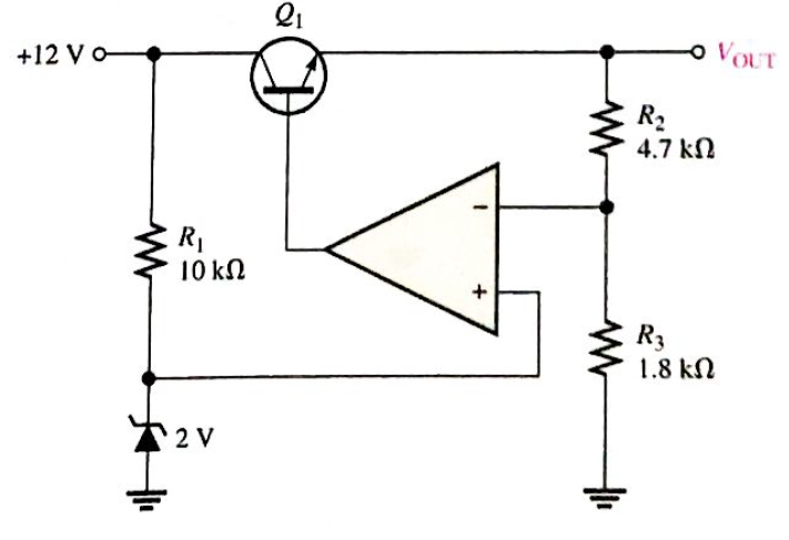
- arm D 01 (1-0) 02) EA w ELL arm B 03 (1-0) 047 D 2 For a 4 Quadrant DC to DC converter (figure above): E - 100 V. with a duty cycle D-0.4. Determine the value of the output voltage EL from A to B 40 V with A being positive with respect to B 20 V with A being positive with respect to B 20 V with A being negative with respect to B 40 V with A being negative with respect to Barrow_forwardPart C: Voltage Regulators 1. Determine the output voltage for the series regulator in Figure 17-46. +12 Vo R₁ 10 kn 2.4 V Q₁ o VOUT R₂ 5.6 kn www R₂ 2.2kQarrow_forwardWhat is the output voltage when the input voltage is 2 mV?arrow_forward
- Please sir all subpart is compulsory please all subpart for like this pleasearrow_forwardwhy does the V(BE) is -0.7 and when input to saturation it change to positivearrow_forwardA certain regulator has a percent load regulation of 1%. a) What is the unloaded output voltage if the full load output is 20 V? b) Determine the output waveform. 120 Vrms ooooo ellle A B R surge W 10 Q2 C 100 uF RL 3.3 ΚΩarrow_forward
- In non inverting amplifier ,the input signal is connected withUpin.arrow_forwardtell me the duty cycle for the above circuit when the output voltage is 24V with input supply of 8V.arrow_forwardto go Determine the output level (maximum positive or maximum negative) for each comparator in Figure 1. Search IF (b) 6 SV (c)arrow_forward
arrow_back_ios
SEE MORE QUESTIONS
arrow_forward_ios
Recommended textbooks for you
 Introductory Circuit Analysis (13th Edition)Electrical EngineeringISBN:9780133923605Author:Robert L. BoylestadPublisher:PEARSON
 Delmar's Standard Textbook Of ElectricityElectrical EngineeringISBN:9781337900348Author:Stephen L. HermanPublisher:Cengage Learning
 Programmable Logic ControllersElectrical EngineeringISBN:9780073373843Author:Frank D. PetruzellaPublisher:McGraw-Hill Education
 Fundamentals of Electric CircuitsElectrical EngineeringISBN:9780078028229Author:Charles K Alexander, Matthew SadikuPublisher:McGraw-Hill Education
 Electric Circuits. (11th Edition)Electrical EngineeringISBN:9780134746968Author:James W. Nilsson, Susan RiedelPublisher:PEARSON
 Engineering ElectromagneticsElectrical EngineeringISBN:9780078028151Author:Hayt, William H. (william Hart), Jr, BUCK, John A.Publisher:Mcgraw-hill Education,
Introductory Circuit Analysis (13th Edition)
Electrical Engineering
ISBN:9780133923605
Author:Robert L. Boylestad
Publisher:PEARSON
Delmar's Standard Textbook Of Electricity
Electrical Engineering
ISBN:9781337900348
Author:Stephen L. Herman
Publisher:Cengage Learning
Programmable Logic Controllers
Electrical Engineering
ISBN:9780073373843
Author:Frank D. Petruzella
Publisher:McGraw-Hill Education
Fundamentals of Electric Circuits
Electrical Engineering
ISBN:9780078028229
Author:Charles K Alexander, Matthew Sadiku
Publisher:McGraw-Hill Education
Electric Circuits. (11th Edition)
Electrical Engineering
ISBN:9780134746968
Author:James W. Nilsson, Susan Riedel
Publisher:PEARSON
Engineering Electromagnetics
Electrical Engineering
ISBN:9780078028151
Author:Hayt, William H. (william Hart), Jr, BUCK, John A.
Publisher:Mcgraw-hill Education,
Designing a sample & hold-circuit from scratch; Author: Moritz Klein;https://www.youtube.com/watch?v=kIJqzkRe4do;License: Standard Youtube License