
Electronics Fundamentals: Circuits, Devices & Applications
8th Edition
ISBN: 9780135072950
Author: Thomas L. Floyd, David Buchla
Publisher: Prentice Hall
expand_more
expand_more
format_list_bulleted
Concept explainers
Videos
Textbook Question
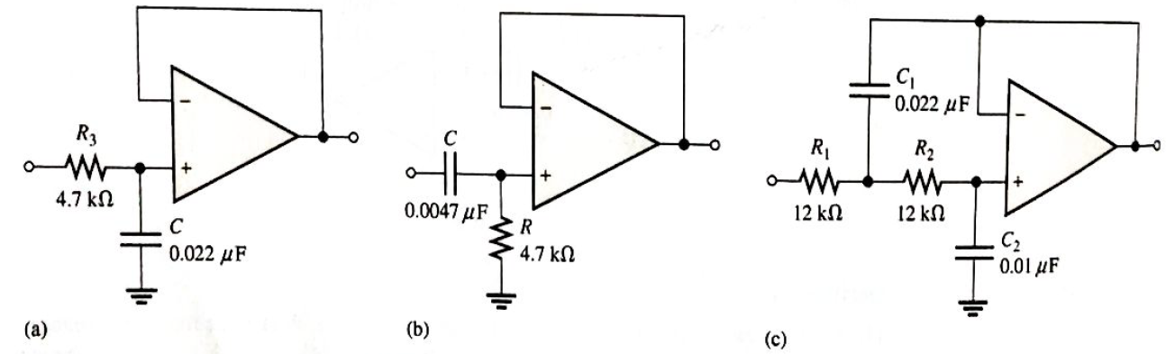
Chapter 19, Problem 18P
Determine the number of poles in each active filter in Figure 19-68, and identify its
Expert Solution & Answer
Want to see the full answer?
Check out a sample textbook solution
Students have asked these similar questions
An A/D converter has the following circuit on its input port.
a.
bandpass filter
b.
high pass filter
c.
Sample and Hold circuit
d.
Low pass filter
e.
Amplifier
1. Find the (Vo) theoretical?
2. Drive the (AV) the integrator?
3. The input of integrator operation is a square wave is 2v, R= 100K,
C-0.luF. calculate vo and draw output wave?
on
For the circuit shown below, if the delay time of each stage is considered to be 50 ns, the
oscillation frequency at the output will be almost
MHZ
HE
VDD
Vout
Chapter 19 Solutions
Electronics Fundamentals: Circuits, Devices & Applications
Ch. 19 - A comparator will have a positive output whenever...Ch. 19 - Prob. 2TFQCh. 19 - Prob. 3TFQCh. 19 - Prob. 4TFQCh. 19 - Prob. 5TFQCh. 19 - The output of a Wien-bridge oscillator is a...Ch. 19 - A Wien-bridge oscillator uses both positive and...Ch. 19 - A two-pole filter has a maximum roll-off rate of...Ch. 19 - Prob. 9TFQCh. 19 - Prob. 10TFQ
Ch. 19 - Prob. 1STCh. 19 - To use a comparator for zero-level detection, the...Ch. 19 - Prob. 3STCh. 19 - Prob. 4STCh. 19 - The gain of the amplifier in Question 4 is -1 -2.2...Ch. 19 - To convert a summing amplifier to an averaging...Ch. 19 - Prob. 7STCh. 19 - Prob. 8STCh. 19 - The feedback path in an op-amp differentiator...Ch. 19 - Prob. 10STCh. 19 - Prob. 11STCh. 19 - Prob. 12STCh. 19 - Determine the output level (maximum positive or...Ch. 19 - A certain op-amp has open-loop gain of 80,000. The...Ch. 19 - Prob. 3PCh. 19 - Determine the output voltage for each circuit in...Ch. 19 - Determine the following in Figure 19—62: VR1 and...Ch. 19 - Find the value of Rf necessary to produce an...Ch. 19 - Find the output voltage when the input voltages...Ch. 19 - Determine the values of the input resistors...Ch. 19 - Determine the rate of change of the output voltage...Ch. 19 - A triangular waveform is applied to the input of...Ch. 19 - Prob. 11PCh. 19 - Calculate the resonant frequency of a lead-lag...Ch. 19 - Determine the JFET drain-to-source resistance in...Ch. 19 - Explain the purpose of D1 in Figure 19-66.Ch. 19 - Find the frequency of oscillation for the...Ch. 19 - What type of signal does the circuit in Figure...Ch. 19 - Prob. 17PCh. 19 - Determine the number of poles in each active...Ch. 19 - Calculate the critical frequencies for the filters...Ch. 19 - Determine the bandwidth and center frequency of...Ch. 19 - Determine the output voltage for the series...Ch. 19 - If R3 in figure 19-70 is doubled, what happens to...Ch. 19 - Prob. 23PCh. 19 - A series voltage regulator with constant-current...Ch. 19 - If R4 (determined in Problem 24) is halved, what...Ch. 19 - In the shunt regulator of Figure 19-72, when the...Ch. 19 - Assume that IL remains constant and VIN increases...Ch. 19 - Open file P19-29; files are found at...Ch. 19 - Open file P19-30 and determine if there is a...
Knowledge Booster


Learn more about
Need a deep-dive on the concept behind this application? Look no further. Learn more about this topic, electrical-engineering and related others by exploring similar questions and additional content below.Similar questions
- Vcc The following biasing network is called IB F RB Via Rc co RE Emitter stabilized bias circuit Fixed bias configuration Collector feedback biasing Voltage divider biasingarrow_forwardVcc The following biasing network is called IB Rc Vi Co RE Collector feedback biasing Emitter stabilized bias circuit Fixed bias configuration Voltage divider biasing DIarrow_forwardFor an SCR di/dt protection is achieved through the use of: O Rin series with SCR O RL in series with SCR O Lin series with SCR O None of thesearrow_forward
- Show the effect of sampling time on the characteristic of ZOH. digital to analog converterarrow_forwardAn integrator has a break frequency of 1 kHz and a unity gain frequency of 10 kHz. Over what frequency range would the circuit integrate a function and increase the signal? O 10 kHz only O1 kHz and below O 10 kHz and above O 1 kHz to 10 kHzarrow_forwardInvestigate what type of filter is the following circuit Determine the implementation of the filter: : "Multiple feedback" or "Sallen-Key".arrow_forward
- 1. Find Icand VCE in the pnp bias circuit. Assume Bpc = 100. VEE +10 V RE 470 N RB 10 k2 RC 330 N -10 V Vccarrow_forward2- Describe the effect of clock frequency on the output af the integrator. 4- Give the advantage and disadvantage of Delta Modulation 5- Compare between Delta Modulation and Pulse Code Modulationarrow_forward2! Cal Culate and draw the out put signal for inverting op amp år cuit if Vin =3Sint-2 Rf=4K Please draw the signal for output voltages R1 =1Karrow_forward
- For the given circuit, what is the minimum peak value of the output waveform if the input waveform is 10V square wave with switching time of 1 second? Assume that the input switches between +10V and -10V DC levels. O - 10 V O - 20 V O ov O -5 Varrow_forwardFor the given circuit, what is the minimum peak value of the output waveform if the input waveform is 10V square wave with switching time of 1 second? Assume that the input switches between +10V and -10V DC levels. O ov O -5V O - 20V O -10Varrow_forwardSelect a frequency of oscillation which can be produced by RC feedback oscillators. O 700kHz O 2MHZ O 3MHZ O None of the given choicesarrow_forward
arrow_back_ios
SEE MORE QUESTIONS
arrow_forward_ios
Recommended textbooks for you
 Introductory Circuit Analysis (13th Edition)Electrical EngineeringISBN:9780133923605Author:Robert L. BoylestadPublisher:PEARSON
 Delmar's Standard Textbook Of ElectricityElectrical EngineeringISBN:9781337900348Author:Stephen L. HermanPublisher:Cengage Learning
 Programmable Logic ControllersElectrical EngineeringISBN:9780073373843Author:Frank D. PetruzellaPublisher:McGraw-Hill Education
 Fundamentals of Electric CircuitsElectrical EngineeringISBN:9780078028229Author:Charles K Alexander, Matthew SadikuPublisher:McGraw-Hill Education
 Electric Circuits. (11th Edition)Electrical EngineeringISBN:9780134746968Author:James W. Nilsson, Susan RiedelPublisher:PEARSON
 Engineering ElectromagneticsElectrical EngineeringISBN:9780078028151Author:Hayt, William H. (william Hart), Jr, BUCK, John A.Publisher:Mcgraw-hill Education,
Introductory Circuit Analysis (13th Edition)
Electrical Engineering
ISBN:9780133923605
Author:Robert L. Boylestad
Publisher:PEARSON
Delmar's Standard Textbook Of Electricity
Electrical Engineering
ISBN:9781337900348
Author:Stephen L. Herman
Publisher:Cengage Learning
Programmable Logic Controllers
Electrical Engineering
ISBN:9780073373843
Author:Frank D. Petruzella
Publisher:McGraw-Hill Education
Fundamentals of Electric Circuits
Electrical Engineering
ISBN:9780078028229
Author:Charles K Alexander, Matthew Sadiku
Publisher:McGraw-Hill Education
Electric Circuits. (11th Edition)
Electrical Engineering
ISBN:9780134746968
Author:James W. Nilsson, Susan Riedel
Publisher:PEARSON
Engineering Electromagnetics
Electrical Engineering
ISBN:9780078028151
Author:Hayt, William H. (william Hart), Jr, BUCK, John A.
Publisher:Mcgraw-hill Education,
What is a Thyristor? - A Galco TV Tech Tip; Author: GalcoTV;https://www.youtube.com/watch?v=LBb_Qz7J3zA;License: Standard Youtube License