
Electronics Fundamentals: Circuits, Devices & Applications
8th Edition
ISBN: 9780135072950
Author: Thomas L. Floyd, David Buchla
Publisher: Prentice Hall
expand_more
expand_more
format_list_bulleted
Videos
Textbook Question
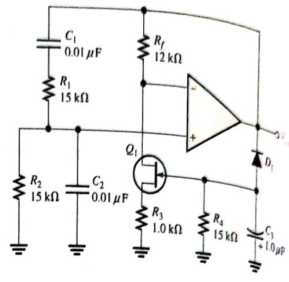
Chapter 19, Problem 14P
Explain the purpose of
Expert Solution & Answer
Want to see the full answer?
Check out a sample textbook solution
Students have asked these similar questions
3. Implement a full adder with 2 4x1 multiplexer
Please sir all subpart is compulsory please all subpart for like this please
Which of the following is not true regarding
clamper?
A positive clamper adds a positive DC voltage
To reduce level shift, reduce the RC value
O A clamper can also be called as a voltage
restorer
O Negative clamper will clamp the positive peak
of output to the reference voltage
Chapter 19 Solutions
Electronics Fundamentals: Circuits, Devices & Applications
Ch. 19 - A comparator will have a positive output whenever...Ch. 19 - Prob. 2TFQCh. 19 - Prob. 3TFQCh. 19 - Prob. 4TFQCh. 19 - Prob. 5TFQCh. 19 - The output of a Wien-bridge oscillator is a...Ch. 19 - A Wien-bridge oscillator uses both positive and...Ch. 19 - A two-pole filter has a maximum roll-off rate of...Ch. 19 - Prob. 9TFQCh. 19 - Prob. 10TFQ
Ch. 19 - Prob. 1STCh. 19 - To use a comparator for zero-level detection, the...Ch. 19 - Prob. 3STCh. 19 - Prob. 4STCh. 19 - The gain of the amplifier in Question 4 is -1 -2.2...Ch. 19 - To convert a summing amplifier to an averaging...Ch. 19 - Prob. 7STCh. 19 - Prob. 8STCh. 19 - The feedback path in an op-amp differentiator...Ch. 19 - Prob. 10STCh. 19 - Prob. 11STCh. 19 - Prob. 12STCh. 19 - Determine the output level (maximum positive or...Ch. 19 - A certain op-amp has open-loop gain of 80,000. The...Ch. 19 - Prob. 3PCh. 19 - Determine the output voltage for each circuit in...Ch. 19 - Determine the following in Figure 19—62: VR1 and...Ch. 19 - Find the value of Rf necessary to produce an...Ch. 19 - Find the output voltage when the input voltages...Ch. 19 - Determine the values of the input resistors...Ch. 19 - Determine the rate of change of the output voltage...Ch. 19 - A triangular waveform is applied to the input of...Ch. 19 - Prob. 11PCh. 19 - Calculate the resonant frequency of a lead-lag...Ch. 19 - Determine the JFET drain-to-source resistance in...Ch. 19 - Explain the purpose of D1 in Figure 19-66.Ch. 19 - Find the frequency of oscillation for the...Ch. 19 - What type of signal does the circuit in Figure...Ch. 19 - Prob. 17PCh. 19 - Determine the number of poles in each active...Ch. 19 - Calculate the critical frequencies for the filters...Ch. 19 - Determine the bandwidth and center frequency of...Ch. 19 - Determine the output voltage for the series...Ch. 19 - If R3 in figure 19-70 is doubled, what happens to...Ch. 19 - Prob. 23PCh. 19 - A series voltage regulator with constant-current...Ch. 19 - If R4 (determined in Problem 24) is halved, what...Ch. 19 - In the shunt regulator of Figure 19-72, when the...Ch. 19 - Assume that IL remains constant and VIN increases...Ch. 19 - Open file P19-29; files are found at...Ch. 19 - Open file P19-30 and determine if there is a...
Knowledge Booster


Learn more about
Need a deep-dive on the concept behind this application? Look no further. Learn more about this topic, electrical-engineering and related others by exploring similar questions and additional content below.Similar questions
- For a Buck converter you need to calculate what range of duty cycles a controller needs to meet the following conditions Input Volatge (from 80V to 120V) DC Needs to output 100V with a 20 Ohm Load The supplied PWN signal is 50 kHz's What is the required range of duty cycles to get the outputarrow_forwardDetermine the output voltage in V WHEN R1= 8kiloohms , r3= 7kohm ,r5=13kohm r7= 120kohms reference voltage of 2.5V and input volatge Vi=2.592Varrow_forwardWhat is the function of the assembly program? AMM PROC CMP AX,97 JL DONE CMP AX,122 JG DONE SUB AX,32 DONE: RET AMM ENDParrow_forward
- Please solve all subpart I will upvote youarrow_forwardFor a certain p-channel JFET, VGS(off) = 6.6 V. The value of VGs in V for midpoint bias is Round your answer to 2 decimal places. Add your answerarrow_forwardWhen in forward biased, what have you noticed when you change the source voltage from 0V to +20V? When in reverse biased, what have you noticed when changing the source voltage from 0 V to -15V?arrow_forward
- The output current equation to voltage to current convertor circuit is Oi_l=v_in/R Oi_l=v_out/R Oi_l=R/v_in O Elsearrow_forwardSimplify to a sum of three terms: A'C'D' + AC' + BCD + A'CD' + A'BC + AB'C'arrow_forwardThe comparator output is low when: • When A is 1000 and B is 1110 • When A is 0101 and B is 0100 • When A is 1101 and B is 1100 O Option 4 In half adder the carry out is O only when the A and B input are : O 10 O : 11 O •01 O . 00 Four bit parallel adder is need full adder O : 5 .2 O 3arrow_forward
- i need help, a upvote will be a givenarrow_forwardHow is the phase-controlled thyristor turned on? Select one: O a. A gate current is applied with VAK >0 O b. A large dv/dt is applied to turn on the thyristor O c. VAK is set above breakdown O d. None of these A single phase full converter is connected to a 120 V 60 Hz supparrow_forwardWhat is the minimum detectable temperature change that the A-to-D converter can resolve?arrow_forward
arrow_back_ios
SEE MORE QUESTIONS
arrow_forward_ios
Recommended textbooks for you
 Introductory Circuit Analysis (13th Edition)Electrical EngineeringISBN:9780133923605Author:Robert L. BoylestadPublisher:PEARSON
 Delmar's Standard Textbook Of ElectricityElectrical EngineeringISBN:9781337900348Author:Stephen L. HermanPublisher:Cengage Learning
 Programmable Logic ControllersElectrical EngineeringISBN:9780073373843Author:Frank D. PetruzellaPublisher:McGraw-Hill Education
 Fundamentals of Electric CircuitsElectrical EngineeringISBN:9780078028229Author:Charles K Alexander, Matthew SadikuPublisher:McGraw-Hill Education
 Electric Circuits. (11th Edition)Electrical EngineeringISBN:9780134746968Author:James W. Nilsson, Susan RiedelPublisher:PEARSON
 Engineering ElectromagneticsElectrical EngineeringISBN:9780078028151Author:Hayt, William H. (william Hart), Jr, BUCK, John A.Publisher:Mcgraw-hill Education,
Introductory Circuit Analysis (13th Edition)
Electrical Engineering
ISBN:9780133923605
Author:Robert L. Boylestad
Publisher:PEARSON
Delmar's Standard Textbook Of Electricity
Electrical Engineering
ISBN:9781337900348
Author:Stephen L. Herman
Publisher:Cengage Learning
Programmable Logic Controllers
Electrical Engineering
ISBN:9780073373843
Author:Frank D. Petruzella
Publisher:McGraw-Hill Education
Fundamentals of Electric Circuits
Electrical Engineering
ISBN:9780078028229
Author:Charles K Alexander, Matthew Sadiku
Publisher:McGraw-Hill Education
Electric Circuits. (11th Edition)
Electrical Engineering
ISBN:9780134746968
Author:James W. Nilsson, Susan Riedel
Publisher:PEARSON
Engineering Electromagnetics
Electrical Engineering
ISBN:9780078028151
Author:Hayt, William H. (william Hart), Jr, BUCK, John A.
Publisher:Mcgraw-hill Education,
Introduction to Logic Gates; Author: Computer Science;https://www.youtube.com/watch?v=fw-N9P38mi4;License: Standard youtube license