
Electronics Fundamentals: Circuits, Devices & Applications
8th Edition
ISBN: 9780135072950
Author: Thomas L. Floyd, David Buchla
Publisher: Prentice Hall
expand_more
expand_more
format_list_bulleted
Videos
Textbook Question
Chapter 19, Problem 24P
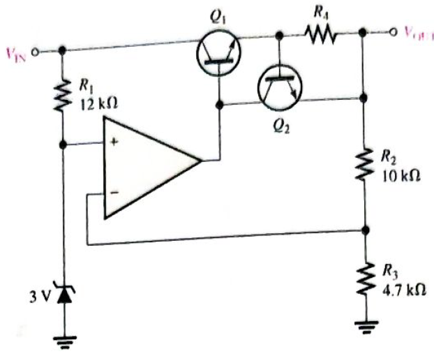
A series voltage regulator with constant-current limiting is shown in Figure 19-71. Determine the value of
Expert Solution & Answer
Want to see the full answer?
Check out a sample textbook solution
Students have asked these similar questions
arm
D 01
(1-0) 02)
EA
w
ELL
arm
B
03 (1-0)
047 D
2
For a 4 Quadrant DC to DC converter (figure above): E - 100 V. with a duty cycle D-0.4. Determine the value of the output
voltage EL from A to B
40 V with A being positive with respect to B
20 V with A being positive with respect to B
20 V with A being negative with respect to B
40 V with A being negative with respect to B
Calculate the dc and ac components of the output signal across load RL in the
circuit of Figure *
Va = 150 V
V, (ms) = 15 V
V's
V', (ms)
R
500 2
Full-wave
rectifier
C,
15 μF
C2
10µF
RL
5 ka
O vdc= 136.4V, Vac= 3.9V
O Vdc= 163.4V, Vac= 9.3V
Vdc= 13.4V, Vac= 9.9V
O None of the above
the way of work buck dc-to-dc converter
Chapter 19 Solutions
Electronics Fundamentals: Circuits, Devices & Applications
Ch. 19 - A comparator will have a positive output whenever...Ch. 19 - Prob. 2TFQCh. 19 - Prob. 3TFQCh. 19 - Prob. 4TFQCh. 19 - Prob. 5TFQCh. 19 - The output of a Wien-bridge oscillator is a...Ch. 19 - A Wien-bridge oscillator uses both positive and...Ch. 19 - A two-pole filter has a maximum roll-off rate of...Ch. 19 - Prob. 9TFQCh. 19 - Prob. 10TFQ
Ch. 19 - Prob. 1STCh. 19 - To use a comparator for zero-level detection, the...Ch. 19 - Prob. 3STCh. 19 - Prob. 4STCh. 19 - The gain of the amplifier in Question 4 is -1 -2.2...Ch. 19 - To convert a summing amplifier to an averaging...Ch. 19 - Prob. 7STCh. 19 - Prob. 8STCh. 19 - The feedback path in an op-amp differentiator...Ch. 19 - Prob. 10STCh. 19 - Prob. 11STCh. 19 - Prob. 12STCh. 19 - Determine the output level (maximum positive or...Ch. 19 - A certain op-amp has open-loop gain of 80,000. The...Ch. 19 - Prob. 3PCh. 19 - Determine the output voltage for each circuit in...Ch. 19 - Determine the following in Figure 19—62: VR1 and...Ch. 19 - Find the value of Rf necessary to produce an...Ch. 19 - Find the output voltage when the input voltages...Ch. 19 - Determine the values of the input resistors...Ch. 19 - Determine the rate of change of the output voltage...Ch. 19 - A triangular waveform is applied to the input of...Ch. 19 - Prob. 11PCh. 19 - Calculate the resonant frequency of a lead-lag...Ch. 19 - Determine the JFET drain-to-source resistance in...Ch. 19 - Explain the purpose of D1 in Figure 19-66.Ch. 19 - Find the frequency of oscillation for the...Ch. 19 - What type of signal does the circuit in Figure...Ch. 19 - Prob. 17PCh. 19 - Determine the number of poles in each active...Ch. 19 - Calculate the critical frequencies for the filters...Ch. 19 - Determine the bandwidth and center frequency of...Ch. 19 - Determine the output voltage for the series...Ch. 19 - If R3 in figure 19-70 is doubled, what happens to...Ch. 19 - Prob. 23PCh. 19 - A series voltage regulator with constant-current...Ch. 19 - If R4 (determined in Problem 24) is halved, what...Ch. 19 - In the shunt regulator of Figure 19-72, when the...Ch. 19 - Assume that IL remains constant and VIN increases...Ch. 19 - Open file P19-29; files are found at...Ch. 19 - Open file P19-30 and determine if there is a...
Knowledge Booster


Learn more about
Need a deep-dive on the concept behind this application? Look no further. Learn more about this topic, electrical-engineering and related others by exploring similar questions and additional content below.Similar questions
- A filtered rectifier has a 15 Vdc output with 100 mVp-p of ripple. The peak output voltage for the circuit is A. 47.2 V peak B. 15.1 Vpeak C. 14.9 Vpeak D. 15.05 Vpeakarrow_forwardAn unloaded zener regulator has asource voltage of 24 V, a series resistance of 470 V with a tolerance of +-5 percent , and a zener voltage of 15 V. What is the zener current?arrow_forwardA certain regulator has a percent load regulation of 1%. a) What is the unloaded output voltage if the full load output is 20 V? b) Determine the output waveform. 120 Vrms ooooo ellle A B R surge W 10 Q2 C 100 uF RL 3.3 ΚΩarrow_forward
- DC to DC converter is shown in the figure. The converter is operating at a switching frequency of 1kHz, duty cycle D=0.5, Find the value of peak current through the diode. D=0.5 200 mH 10 A to 200 V 11 C Loadarrow_forwardRefer to the following figure. The circuit is a @ Battl www Oa. Positive limiter with positive bias O b. Negative clamper OC. Negative limiter with negative bias Od. Positive clamperarrow_forwardDesign a zener regulator to meet these specifications: 1. Load voltage is 6.8 V 2. Source Voltage is 20 V 3. Load current is 30 mAarrow_forward
- 4. Determine the ripple factor for the filtered bridge rectifier with a load as indicated in figure. Vp = 0.7 v₁ 120 V rms 60 Hz Vpipri) 10:1 Posec's D₂ D₁ DA C 1000μF Output RL 220 (2arrow_forwardDifine the diodd and explain it’s basing conditionsarrow_forwardThe initial delay of 30 degree replaced by 20 degree, in three phase half wave controlled converter with RL load, if T2 is triggered at 200 degree, what may be the firing angle of the converter? a. 120 degree b. 60 degree O c. 20 degree O d. 80 degreearrow_forward
- (B) Calculate the current through the zener diode for the given values of load resistance in this circuit: 1- Rioad =2 k2 2- Ricad=3 k2 Reries 2.2 k2 Vsoce= 30 V Vz= 12.5 Varrow_forwardWhen the positive terminal of a digital dc voltmeter is connected at the Vo terminal and negative terminal to ground in the figure shown with the diode approximation, the reading of the meter is 12.7V 6.985 R1 2.7k -6.985 V 6.6 V -6.6 V Si R2 3.3k Voarrow_forwardDesign a Buck Converter with the Following Features. Input Voltage = 50 V Output Voltage = 20 V Switching Frequency=6 KHz Output Power = 300 W Efficiency =%85 Current fluctuationı <%10*Input current Output Voltage Ripple<%1*Output Voltagearrow_forward
arrow_back_ios
SEE MORE QUESTIONS
arrow_forward_ios
Recommended textbooks for you
 Introductory Circuit Analysis (13th Edition)Electrical EngineeringISBN:9780133923605Author:Robert L. BoylestadPublisher:PEARSON
 Delmar's Standard Textbook Of ElectricityElectrical EngineeringISBN:9781337900348Author:Stephen L. HermanPublisher:Cengage Learning
 Programmable Logic ControllersElectrical EngineeringISBN:9780073373843Author:Frank D. PetruzellaPublisher:McGraw-Hill Education
 Fundamentals of Electric CircuitsElectrical EngineeringISBN:9780078028229Author:Charles K Alexander, Matthew SadikuPublisher:McGraw-Hill Education
 Electric Circuits. (11th Edition)Electrical EngineeringISBN:9780134746968Author:James W. Nilsson, Susan RiedelPublisher:PEARSON
 Engineering ElectromagneticsElectrical EngineeringISBN:9780078028151Author:Hayt, William H. (william Hart), Jr, BUCK, John A.Publisher:Mcgraw-hill Education,
Introductory Circuit Analysis (13th Edition)
Electrical Engineering
ISBN:9780133923605
Author:Robert L. Boylestad
Publisher:PEARSON
Delmar's Standard Textbook Of Electricity
Electrical Engineering
ISBN:9781337900348
Author:Stephen L. Herman
Publisher:Cengage Learning
Programmable Logic Controllers
Electrical Engineering
ISBN:9780073373843
Author:Frank D. Petruzella
Publisher:McGraw-Hill Education
Fundamentals of Electric Circuits
Electrical Engineering
ISBN:9780078028229
Author:Charles K Alexander, Matthew Sadiku
Publisher:McGraw-Hill Education
Electric Circuits. (11th Edition)
Electrical Engineering
ISBN:9780134746968
Author:James W. Nilsson, Susan Riedel
Publisher:PEARSON
Engineering Electromagnetics
Electrical Engineering
ISBN:9780078028151
Author:Hayt, William H. (william Hart), Jr, BUCK, John A.
Publisher:Mcgraw-hill Education,
Introduction to Logic Gates; Author: Computer Science;https://www.youtube.com/watch?v=fw-N9P38mi4;License: Standard youtube license