
Electronics Fundamentals: Circuits, Devices & Applications
8th Edition
ISBN: 9780135072950
Author: Thomas L. Floyd, David Buchla
Publisher: Prentice Hall
expand_more
expand_more
format_list_bulleted
Videos
Textbook Question
Chapter 19, Problem 16P
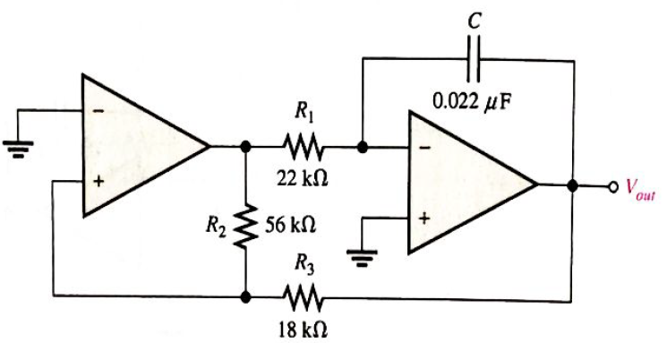
What type of signal does the circuit in Figure 19-67 produce? Determine the frequency of the output.
Expert Solution & Answer
Want to see the full answer?
Check out a sample textbook solution
Students have asked these similar questions
design a triangular wave oscillator with oscillation frequency of (50 KHz) andtriangle wave has Vp-p = 6v with Vcc= 18v draw circuit and output waves (vo1 andVo2)
For the given circuit, what is the minimum peak value of the output waveform if the input waveform is 10V square wave
with switching time of 1 second? Assume that the input switches between +10V and -10V DC levels.
O V
-5 V
-10 V
-20 V
2. Draw and explain the difference between clipper circuit and clamper circuit output
waveform
Chapter 19 Solutions
Electronics Fundamentals: Circuits, Devices & Applications
Ch. 19 - A comparator will have a positive output whenever...Ch. 19 - Prob. 2TFQCh. 19 - Prob. 3TFQCh. 19 - Prob. 4TFQCh. 19 - Prob. 5TFQCh. 19 - The output of a Wien-bridge oscillator is a...Ch. 19 - A Wien-bridge oscillator uses both positive and...Ch. 19 - A two-pole filter has a maximum roll-off rate of...Ch. 19 - Prob. 9TFQCh. 19 - Prob. 10TFQ
Ch. 19 - Prob. 1STCh. 19 - To use a comparator for zero-level detection, the...Ch. 19 - Prob. 3STCh. 19 - Prob. 4STCh. 19 - The gain of the amplifier in Question 4 is -1 -2.2...Ch. 19 - To convert a summing amplifier to an averaging...Ch. 19 - Prob. 7STCh. 19 - Prob. 8STCh. 19 - The feedback path in an op-amp differentiator...Ch. 19 - Prob. 10STCh. 19 - Prob. 11STCh. 19 - Prob. 12STCh. 19 - Determine the output level (maximum positive or...Ch. 19 - A certain op-amp has open-loop gain of 80,000. The...Ch. 19 - Prob. 3PCh. 19 - Determine the output voltage for each circuit in...Ch. 19 - Determine the following in Figure 19—62: VR1 and...Ch. 19 - Find the value of Rf necessary to produce an...Ch. 19 - Find the output voltage when the input voltages...Ch. 19 - Determine the values of the input resistors...Ch. 19 - Determine the rate of change of the output voltage...Ch. 19 - A triangular waveform is applied to the input of...Ch. 19 - Prob. 11PCh. 19 - Calculate the resonant frequency of a lead-lag...Ch. 19 - Determine the JFET drain-to-source resistance in...Ch. 19 - Explain the purpose of D1 in Figure 19-66.Ch. 19 - Find the frequency of oscillation for the...Ch. 19 - What type of signal does the circuit in Figure...Ch. 19 - Prob. 17PCh. 19 - Determine the number of poles in each active...Ch. 19 - Calculate the critical frequencies for the filters...Ch. 19 - Determine the bandwidth and center frequency of...Ch. 19 - Determine the output voltage for the series...Ch. 19 - If R3 in figure 19-70 is doubled, what happens to...Ch. 19 - Prob. 23PCh. 19 - A series voltage regulator with constant-current...Ch. 19 - If R4 (determined in Problem 24) is halved, what...Ch. 19 - In the shunt regulator of Figure 19-72, when the...Ch. 19 - Assume that IL remains constant and VIN increases...Ch. 19 - Open file P19-29; files are found at...Ch. 19 - Open file P19-30 and determine if there is a...
Knowledge Booster


Learn more about
Need a deep-dive on the concept behind this application? Look no further. Learn more about this topic, electrical-engineering and related others by exploring similar questions and additional content below.Similar questions
- For a Buck converter you need to calculate what range of duty cycles a controller needs to meet the following conditions Input Volatge (from 80V to 120V) DC Needs to output 100V with a 20 Ohm Load The supplied PWN signal is 50 kHz's What is the required range of duty cycles to get the outputarrow_forwardHow can the amplitude of the output voltage be increased?arrow_forwardDetermine the most likely fault(s) for each of the following symptoms in Figure 12-75 with a 100 mV signal applied. (a) No output signal. (b) Output severely clipped on both positive and negative swings. R2 10 k R1 1.0 karrow_forward
- Class C commutation technique is forced commutation technique O complementary commutation technique voltage commutation technique O All of them O In class C commutation technique to turn off the SCR T1 gate pulse is given to SCR T1 O gate pulse is given to SCR T2 collector pulse is given to SCR T1 collector pulse is given to SCR T2 Oarrow_forwardwhat is the output voltage without any changes?arrow_forwardWHAT ARE FREQUENCY DEMODULATORSarrow_forward
- Q2. Consider the following RISC-V loop: (i) (ii) (iii) (iv) (iv) (v) (vi) (vii) LOOP: beq x6, addi x6, x6, -1 add x11, x11, x5 addi x5, x5, 2 slli x7, x5, 1 beq x0, x0, LOOP beq x11, x0, DONE 2 | Page Assume that the register x6 is initialized to the value 5, x5 and x7 to the value 0, and x11 to the last digit of your student ID. All these initializations are performed using RISC-V instructions. Fill out the table below. Final value of x5 at the end of execution Final value of x7 at the end of execution Total number of instructions executed DONE: add x12, x11, x19 microarchitecture x0, DONE Number of cycles needed to execute these instructions in a single cycle microarchitecture Number of cycles needed to execute these instructions in a multi-cyclearrow_forward* Which circuit is changing the shape of the input Clamper circuit O Clipper circuit O None Oarrow_forwardChange the MOD-8 counter in Figure to a MOD-16 counter, and connect the MSB to the multiplexer E input. Draw the Z waveform. 1 ΚΩ +Vcc W 13 1₂ lo Eight-input multiplexer 74HC151 SSS 17 $₂ S₁ So MOD-8 CLK- counter •JMMarrow_forward
- A filtered rectifier has a 15 Vdc output with 100 mVp-p of ripple. The peak output voltage for the circuit is A. 47.2 V peak B. 15.1 Vpeak C. 14.9 Vpeak D. 15.05 Vpeakarrow_forwardarm D 01 (1-0) 02) EA w ELL arm B 03 (1-0) 047 D 2 For a 4 Quadrant DC to DC converter (figure above): E - 100 V. with a duty cycle D-0.4. Determine the value of the output voltage EL from A to B 40 V with A being positive with respect to B 20 V with A being positive with respect to B 20 V with A being negative with respect to B 40 V with A being negative with respect to Barrow_forwardDesign a Buck Converter with the Following Features. Input Voltage = 50 V Output Voltage = 20 V Switching Frequency=6 KHz Output Power = 300 W Efficiency =%85 Current fluctuationı <%10*Input current Output Voltage Ripple<%1*Output Voltagearrow_forward
arrow_back_ios
SEE MORE QUESTIONS
arrow_forward_ios
Recommended textbooks for you
 Introductory Circuit Analysis (13th Edition)Electrical EngineeringISBN:9780133923605Author:Robert L. BoylestadPublisher:PEARSON
 Delmar's Standard Textbook Of ElectricityElectrical EngineeringISBN:9781337900348Author:Stephen L. HermanPublisher:Cengage Learning
 Programmable Logic ControllersElectrical EngineeringISBN:9780073373843Author:Frank D. PetruzellaPublisher:McGraw-Hill Education
 Fundamentals of Electric CircuitsElectrical EngineeringISBN:9780078028229Author:Charles K Alexander, Matthew SadikuPublisher:McGraw-Hill Education
 Electric Circuits. (11th Edition)Electrical EngineeringISBN:9780134746968Author:James W. Nilsson, Susan RiedelPublisher:PEARSON
 Engineering ElectromagneticsElectrical EngineeringISBN:9780078028151Author:Hayt, William H. (william Hart), Jr, BUCK, John A.Publisher:Mcgraw-hill Education,
Introductory Circuit Analysis (13th Edition)
Electrical Engineering
ISBN:9780133923605
Author:Robert L. Boylestad
Publisher:PEARSON
Delmar's Standard Textbook Of Electricity
Electrical Engineering
ISBN:9781337900348
Author:Stephen L. Herman
Publisher:Cengage Learning
Programmable Logic Controllers
Electrical Engineering
ISBN:9780073373843
Author:Frank D. Petruzella
Publisher:McGraw-Hill Education
Fundamentals of Electric Circuits
Electrical Engineering
ISBN:9780078028229
Author:Charles K Alexander, Matthew Sadiku
Publisher:McGraw-Hill Education
Electric Circuits. (11th Edition)
Electrical Engineering
ISBN:9780134746968
Author:James W. Nilsson, Susan Riedel
Publisher:PEARSON
Engineering Electromagnetics
Electrical Engineering
ISBN:9780078028151
Author:Hayt, William H. (william Hart), Jr, BUCK, John A.
Publisher:Mcgraw-hill Education,
Introduction to Logic Gates; Author: Computer Science;https://www.youtube.com/watch?v=fw-N9P38mi4;License: Standard youtube license