
Electronics Fundamentals: Circuits, Devices & Applications
8th Edition
ISBN: 9780135072950
Author: Thomas L. Floyd, David Buchla
Publisher: Prentice Hall
expand_more
expand_more
format_list_bulleted
Videos
Textbook Question
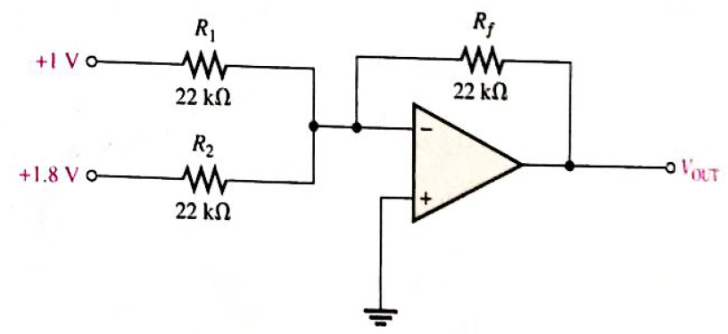
Chapter 19, Problem 5P
Determine the following in Figure 19—62:
-
- current through
-
Expert Solution & Answer
Want to see the full answer?
Check out a sample textbook solution
Students have asked these similar questions
Using phone hand
I need expert handwritten solutions
Show handwriting solutions not Ai
Chapter 19 Solutions
Electronics Fundamentals: Circuits, Devices & Applications
Ch. 19 - A comparator will have a positive output whenever...Ch. 19 - Prob. 2TFQCh. 19 - Prob. 3TFQCh. 19 - Prob. 4TFQCh. 19 - Prob. 5TFQCh. 19 - The output of a Wien-bridge oscillator is a...Ch. 19 - A Wien-bridge oscillator uses both positive and...Ch. 19 - A two-pole filter has a maximum roll-off rate of...Ch. 19 - Prob. 9TFQCh. 19 - Prob. 10TFQ
Ch. 19 - Prob. 1STCh. 19 - To use a comparator for zero-level detection, the...Ch. 19 - Prob. 3STCh. 19 - Prob. 4STCh. 19 - The gain of the amplifier in Question 4 is -1 -2.2...Ch. 19 - To convert a summing amplifier to an averaging...Ch. 19 - Prob. 7STCh. 19 - Prob. 8STCh. 19 - The feedback path in an op-amp differentiator...Ch. 19 - Prob. 10STCh. 19 - Prob. 11STCh. 19 - Prob. 12STCh. 19 - Determine the output level (maximum positive or...Ch. 19 - A certain op-amp has open-loop gain of 80,000. The...Ch. 19 - Prob. 3PCh. 19 - Determine the output voltage for each circuit in...Ch. 19 - Determine the following in Figure 19—62: VR1 and...Ch. 19 - Find the value of Rf necessary to produce an...Ch. 19 - Find the output voltage when the input voltages...Ch. 19 - Determine the values of the input resistors...Ch. 19 - Determine the rate of change of the output voltage...Ch. 19 - A triangular waveform is applied to the input of...Ch. 19 - Prob. 11PCh. 19 - Calculate the resonant frequency of a lead-lag...Ch. 19 - Determine the JFET drain-to-source resistance in...Ch. 19 - Explain the purpose of D1 in Figure 19-66.Ch. 19 - Find the frequency of oscillation for the...Ch. 19 - What type of signal does the circuit in Figure...Ch. 19 - Prob. 17PCh. 19 - Determine the number of poles in each active...Ch. 19 - Calculate the critical frequencies for the filters...Ch. 19 - Determine the bandwidth and center frequency of...Ch. 19 - Determine the output voltage for the series...Ch. 19 - If R3 in figure 19-70 is doubled, what happens to...Ch. 19 - Prob. 23PCh. 19 - A series voltage regulator with constant-current...Ch. 19 - If R4 (determined in Problem 24) is halved, what...Ch. 19 - In the shunt regulator of Figure 19-72, when the...Ch. 19 - Assume that IL remains constant and VIN increases...Ch. 19 - Open file P19-29; files are found at...Ch. 19 - Open file P19-30 and determine if there is a...
Knowledge Booster


Learn more about
Need a deep-dive on the concept behind this application? Look no further. Learn more about this topic, electrical-engineering and related others by exploring similar questions and additional content below.Similar questions
- Maul Dulde Questio119 819 PREV NEXT In the lab, you have setup a thermocouple and have used a thermistor along with an ice bath and water at various temperatures (confirmed with the thermistor) up to 100 degrees Celsius for calibration. The calibration data is shown in the table below and the full-scale output range is 0-5 mV. You note that there is scatter in your data; however, you must use a linear curve fit to efficiently process the measurements during an automated temperature measurement process. Question 1 100% Question 2 100% Question 3 100% Question 4 100% Question 5 100% Question 6 100% mV The slope of your linear calibration curve for the thermocouple is 0.0334 °C with an offset of -0.07 mV. Question 7 100% Question 8 100% What is the maximum expected linearity error as a percentage of the full-scale output? Question 9 0% Summary -0.08 Thermocouple Calibration Data Temperature (°C) Voltage (in mV) 0 20 20 40 40 60 60 60 80 96 90 0.587 1.314 1.901 2.528 2.782 100 3.055 LIT…arrow_forwardOnly expert should solve itarrow_forwardWhat is the high cutoff frequency? What is the low cutoff frequency? What is the bandwidth?arrow_forward
- Need handwritten pen and paper solution do not use chatgpt or AI otherwise downvote. An AC motor with impedance Z₁ = 4.2 + j3.6 ohm is supplied from a source of 220 V at 60 Hz. Find: a) pf, P and Q, b) Determine the capacitor required to connect in parallel with the motor so that the power factor is corrected and equal to 0.98 behind.arrow_forwardNeed handwritten pen and paper solution do not use chatgpt or AI otherwise downvote An AC motor with impedance Z₁ = 4.2 + j3.6 ohm is supplied from a source of 220 V at 60 Hz. Find: a) pf, P and Q, b) Determine the capacitor required to connect in parallel with the motor so that the power factor is corrected and equal to 0.98 behind.arrow_forwardFind;- magnitude of line voltages Line currents Verify that th eload is balanced, i.e In = 0arrow_forward
- Don't use ai to answer I will report you answerarrow_forwardDon't use ai to answer I will report you answerarrow_forward(b) Below is a FSM with a 1-bit input A, and a 1-bit output Y. Deter- mine the combined state and output table. Identify the unreachable states, and sketch the state-transition diagram. In your table and diagram, use Os and 1s for the states and next states, not symbols like S0, S1, etc. A D D D CLK S'₁₂ S2 S₁₁ S1 Y S' r So S2 S₁ So resetarrow_forward
- Do by pen and paper not using chatgpt Determine the output current of E1 in the circuit shown in . The voltage drop of the diodes is 0.7 V.arrow_forwardDon't use ai to answer I will report you answerarrow_forwardFor the amplifier shown, if β = 150: Calculate the input impedance at the base. Calculate the input impedance of the stage.arrow_forward
arrow_back_ios
SEE MORE QUESTIONS
arrow_forward_ios
Recommended textbooks for you
 Electricity for Refrigeration, Heating, and Air C...Mechanical EngineeringISBN:9781337399128Author:Russell E. SmithPublisher:Cengage Learning
 Delmar's Standard Textbook Of ElectricityElectrical EngineeringISBN:9781337900348Author:Stephen L. HermanPublisher:Cengage Learning
Electricity for Refrigeration, Heating, and Air C...
Mechanical Engineering
ISBN:9781337399128
Author:Russell E. Smith
Publisher:Cengage Learning
Delmar's Standard Textbook Of Electricity
Electrical Engineering
ISBN:9781337900348
Author:Stephen L. Herman
Publisher:Cengage Learning
Lead and lag compensation using Bode diagrams; Author: John Rossiter;https://www.youtube.com/watch?v=UBE-Tp173vk;License: Standard Youtube License