
Electronics Fundamentals: Circuits, Devices & Applications
8th Edition
ISBN: 9780135072950
Author: Thomas L. Floyd, David Buchla
Publisher: Prentice Hall
expand_more
expand_more
format_list_bulleted
Concept explainers
Videos
Textbook Question
Chapter 19, Problem 7P
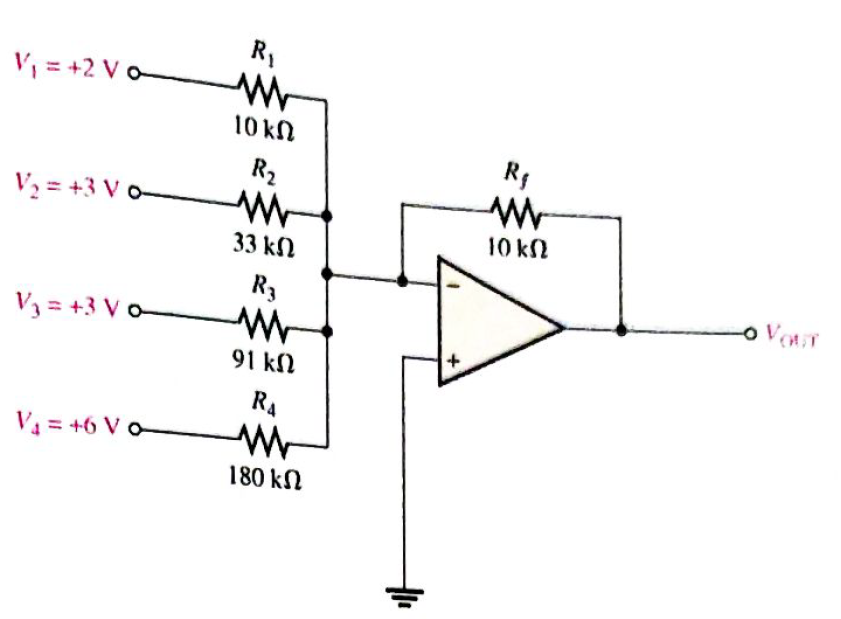
Find the output voltage when the input voltages shown in Figure 19-63 are applied to the scaling adder. What is the current through
Expert Solution & Answer
Want to see the full answer?
Check out a sample textbook solution
Students have asked these similar questions
In what region the following circuit will be in?
+1.8 V
o VD
O a. Triode
O b. None- off the options
O c. Saturation
O d. Cut-off
Determine the most likely fault(s) for each of the following symptoms in Figure 12-75 with a
100 mV signal applied.
(a) No output signal.
(b) Output severely clipped on both positive and negative swings.
R2
10 k
R1
1.0 k
For a Buck converter you need to calculate what range of duty cycles a controller needs to meet the following conditions
Input Volatge (from 80V to 120V) DC
Needs to output 100V with a 20 Ohm Load
The supplied PWN signal is 50 kHz's
What is the required range of duty cycles to get the output
Chapter 19 Solutions
Electronics Fundamentals: Circuits, Devices & Applications
Ch. 19 - A comparator will have a positive output whenever...Ch. 19 - Prob. 2TFQCh. 19 - Prob. 3TFQCh. 19 - Prob. 4TFQCh. 19 - Prob. 5TFQCh. 19 - The output of a Wien-bridge oscillator is a...Ch. 19 - A Wien-bridge oscillator uses both positive and...Ch. 19 - A two-pole filter has a maximum roll-off rate of...Ch. 19 - Prob. 9TFQCh. 19 - Prob. 10TFQ
Ch. 19 - Prob. 1STCh. 19 - To use a comparator for zero-level detection, the...Ch. 19 - Prob. 3STCh. 19 - Prob. 4STCh. 19 - The gain of the amplifier in Question 4 is -1 -2.2...Ch. 19 - To convert a summing amplifier to an averaging...Ch. 19 - Prob. 7STCh. 19 - Prob. 8STCh. 19 - The feedback path in an op-amp differentiator...Ch. 19 - Prob. 10STCh. 19 - Prob. 11STCh. 19 - Prob. 12STCh. 19 - Determine the output level (maximum positive or...Ch. 19 - A certain op-amp has open-loop gain of 80,000. The...Ch. 19 - Prob. 3PCh. 19 - Determine the output voltage for each circuit in...Ch. 19 - Determine the following in Figure 19—62: VR1 and...Ch. 19 - Find the value of Rf necessary to produce an...Ch. 19 - Find the output voltage when the input voltages...Ch. 19 - Determine the values of the input resistors...Ch. 19 - Determine the rate of change of the output voltage...Ch. 19 - A triangular waveform is applied to the input of...Ch. 19 - Prob. 11PCh. 19 - Calculate the resonant frequency of a lead-lag...Ch. 19 - Determine the JFET drain-to-source resistance in...Ch. 19 - Explain the purpose of D1 in Figure 19-66.Ch. 19 - Find the frequency of oscillation for the...Ch. 19 - What type of signal does the circuit in Figure...Ch. 19 - Prob. 17PCh. 19 - Determine the number of poles in each active...Ch. 19 - Calculate the critical frequencies for the filters...Ch. 19 - Determine the bandwidth and center frequency of...Ch. 19 - Determine the output voltage for the series...Ch. 19 - If R3 in figure 19-70 is doubled, what happens to...Ch. 19 - Prob. 23PCh. 19 - A series voltage regulator with constant-current...Ch. 19 - If R4 (determined in Problem 24) is halved, what...Ch. 19 - In the shunt regulator of Figure 19-72, when the...Ch. 19 - Assume that IL remains constant and VIN increases...Ch. 19 - Open file P19-29; files are found at...Ch. 19 - Open file P19-30 and determine if there is a...
Knowledge Booster


Learn more about
Need a deep-dive on the concept behind this application? Look no further. Learn more about this topic, electrical-engineering and related others by exploring similar questions and additional content below.Similar questions
- hil E 3. Identify the type of input mode for each op-amp in Figure 12-61. Val Figure 12-61 4. A certain op-amp has a CMRR of 250,000. Convert this to decibels. ▸arrow_forward18. Determine the approximate values for each of the following quantities in Figure 12-67. (a) (b) ! (c) Vout (d) closed-loop gain FIGURE 12-67 R 22 kfl R, 2.2 klarrow_forwardHow is the phase-controlled thyristor turned on? Select one: O a. A gate current is applied with VAK >0 O b. A large dv/dt is applied to turn on the thyristor O c. VAK is set above breakdown O d. None of these A single phase full converter is connected to a 120 V 60 Hz supparrow_forward
- why does the V(BE) is -0.7 and when input to saturation it change to positivearrow_forwardFor the given circuit, what is the minimum peak value of the output waveform if the input waveform is 10V square wave with switching time of 1 second? Assume that the input switches between +10V and -10V DC levels. O V -5 V -10 V -20 Varrow_forwardAlthough current is blocked in reverse bias, (a) there is some current due to majority carriers (b) there is a very small current due to minority carriers (c) there is an avalanche currentarrow_forward
- Natural commutation circuit is takes place when O Voltage across the device becomes negative O Voltage across the device becomes positive O gate current becomes zero O anode current becomes Zero commutation is usually used in converters O line O load O forced O external - phasearrow_forwardDraw the output waveform for the comparator circuit in figure below. Assume that Q? +Vout(max) = +10 V and Vout(max) = -10V. Vin U1 Vout R1 +3 V 80ko 0- R2 20ko Con'larrow_forwardIn a flash A/D converter, the priority * encoder is used to select the first input O select the highest value input select the lowest value input O select the last input Oarrow_forward
- Change the MOD-8 counter in Figure to a MOD-16 counter, and connect the MSB to the multiplexer E input. Draw the Z waveform. 1 ΚΩ +Vcc W 13 1₂ lo Eight-input multiplexer 74HC151 SSS 17 $₂ S₁ So MOD-8 CLK- counter •JMMarrow_forwardarm D 01 (1-0) 02) EA w ELL arm B 03 (1-0) 047 D 2 For a 4 Quadrant DC to DC converter (figure above): E - 100 V. with a duty cycle D-0.4. Determine the value of the output voltage EL from A to B 40 V with A being positive with respect to B 20 V with A being positive with respect to B 20 V with A being negative with respect to B 40 V with A being negative with respect to Barrow_forwardVoltage multipliers take an ac input voltage, and provide an ac output voltage that is a multiple of the input an ac output twice the input none of these a dc output voltage that is a multiple of the inputarrow_forward
arrow_back_ios
SEE MORE QUESTIONS
arrow_forward_ios
Recommended textbooks for you
 Introductory Circuit Analysis (13th Edition)Electrical EngineeringISBN:9780133923605Author:Robert L. BoylestadPublisher:PEARSON
 Delmar's Standard Textbook Of ElectricityElectrical EngineeringISBN:9781337900348Author:Stephen L. HermanPublisher:Cengage Learning
 Programmable Logic ControllersElectrical EngineeringISBN:9780073373843Author:Frank D. PetruzellaPublisher:McGraw-Hill Education
 Fundamentals of Electric CircuitsElectrical EngineeringISBN:9780078028229Author:Charles K Alexander, Matthew SadikuPublisher:McGraw-Hill Education
 Electric Circuits. (11th Edition)Electrical EngineeringISBN:9780134746968Author:James W. Nilsson, Susan RiedelPublisher:PEARSON
 Engineering ElectromagneticsElectrical EngineeringISBN:9780078028151Author:Hayt, William H. (william Hart), Jr, BUCK, John A.Publisher:Mcgraw-hill Education,
Introductory Circuit Analysis (13th Edition)
Electrical Engineering
ISBN:9780133923605
Author:Robert L. Boylestad
Publisher:PEARSON
Delmar's Standard Textbook Of Electricity
Electrical Engineering
ISBN:9781337900348
Author:Stephen L. Herman
Publisher:Cengage Learning
Programmable Logic Controllers
Electrical Engineering
ISBN:9780073373843
Author:Frank D. Petruzella
Publisher:McGraw-Hill Education
Fundamentals of Electric Circuits
Electrical Engineering
ISBN:9780078028229
Author:Charles K Alexander, Matthew Sadiku
Publisher:McGraw-Hill Education
Electric Circuits. (11th Edition)
Electrical Engineering
ISBN:9780134746968
Author:James W. Nilsson, Susan Riedel
Publisher:PEARSON
Engineering Electromagnetics
Electrical Engineering
ISBN:9780078028151
Author:Hayt, William H. (william Hart), Jr, BUCK, John A.
Publisher:Mcgraw-hill Education,
Designing a sample & hold-circuit from scratch; Author: Moritz Klein;https://www.youtube.com/watch?v=kIJqzkRe4do;License: Standard Youtube License